
Ranger 2WD L4-2.3L (2009)
-
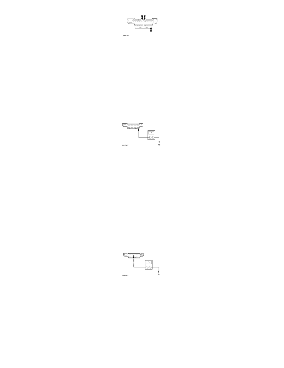
Are DLC pins 4, 5 and 16 OK?
Yes
GO to K2.
No
REPAIR the DLC as necessary. CLEAR the DTCs. REPEAT the network test with the scan tool.
-------------------------------------------------
K2 CHECK THE DLC VOLTAGE SUPPLY CIRCUITS FOR AN OPEN
-
Measure the voltage between the DLC C251-16, circuit SBP29 (GY/RD), harness side and ground.
-
Is the voltage greater than 10 volts?
Yes
GO to K3.
No
VERIFY the Smart Junction Box (SJB) fuse 29 (20A) is OK. If OK, REPAIR the circuit. If not OK, REFER to the Wiring Diagrams to identify the
possible causes of the circuit short. CLEAR the
DTCs. REPEAT the network test with the scan tool.
-------------------------------------------------
K3 CHECK THE DLC GROUND CIRCUITS FOR AN OPEN
-
Disconnect: Negative Battery Cable.
-
Measure the resistance between the DLC C251-4, circuit GD161 (BK/YE), harness side and ground; and between the DLC C251-5, circuit GD174
(BK/WH), harness side and ground.
-
Are the resistances less than 5 ohms?
Yes
REPAIR the scan tool. CONNECT the negative battery cable. REPEAT the network test with the scan tool.
No
REPAIR the circuit in question. CONNECT the negative battery cable. CLEAR the DTCs. REPEAT the network test with the scan tool.
-------------------------------------------------