
Ranger 2WD V6-182 3.0L (1995)
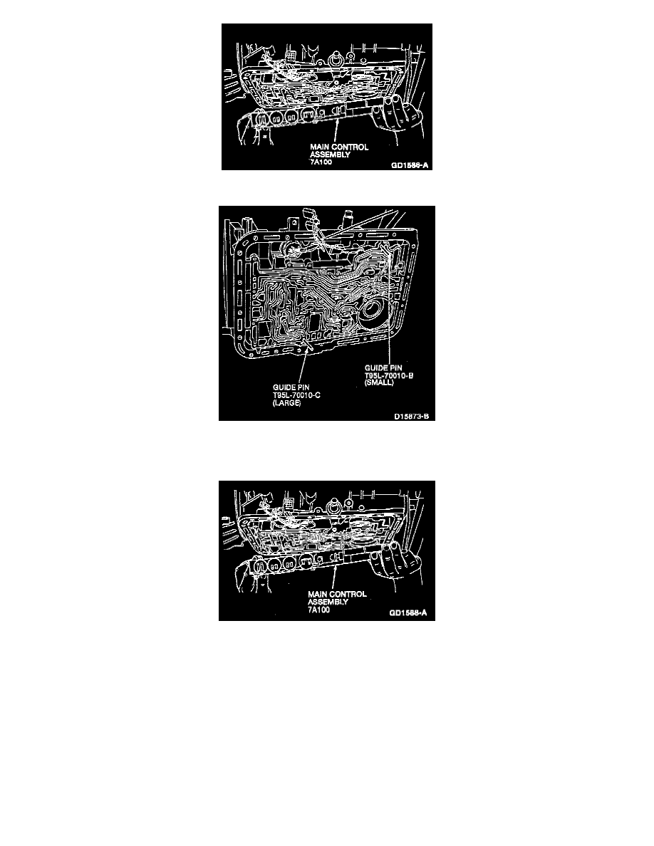
7. Remove the main control assembly.
8. Install the guide pins into the case in the positions shown.
9. Install new separator to case gasket.
10. NOTE: Make sure main control assembly gasket is properly aligned.
Install the main control assembly on the case. Align the manual valve with the manual valve inner lever pin as shown.
11. Install four M6 x 45mm screws in locations A. Finger tighten.
12. Install two M6 x 35mm main control assembly-to-case screws in locations B. Finger tighten.
13. Install one M6 x 30mm main control assembly-to-case screws in location C. Finger tighten.
14. Remove both valve body guide pins T95L-70010-B and T95L-70010-C.
15. Install sixteen M6 x 40mm main control assembly-to-case screws in locations D. Finger tighten.