
Ranger 2WD V6-245 4.0L (1990)
Ignition Lock: Service and Repair
With Key
The following procedure applies to vehicles that have functional lock cylinders, ignition keys available for the vehicle, or ignition key numbers that are
known and the proper key can be made.
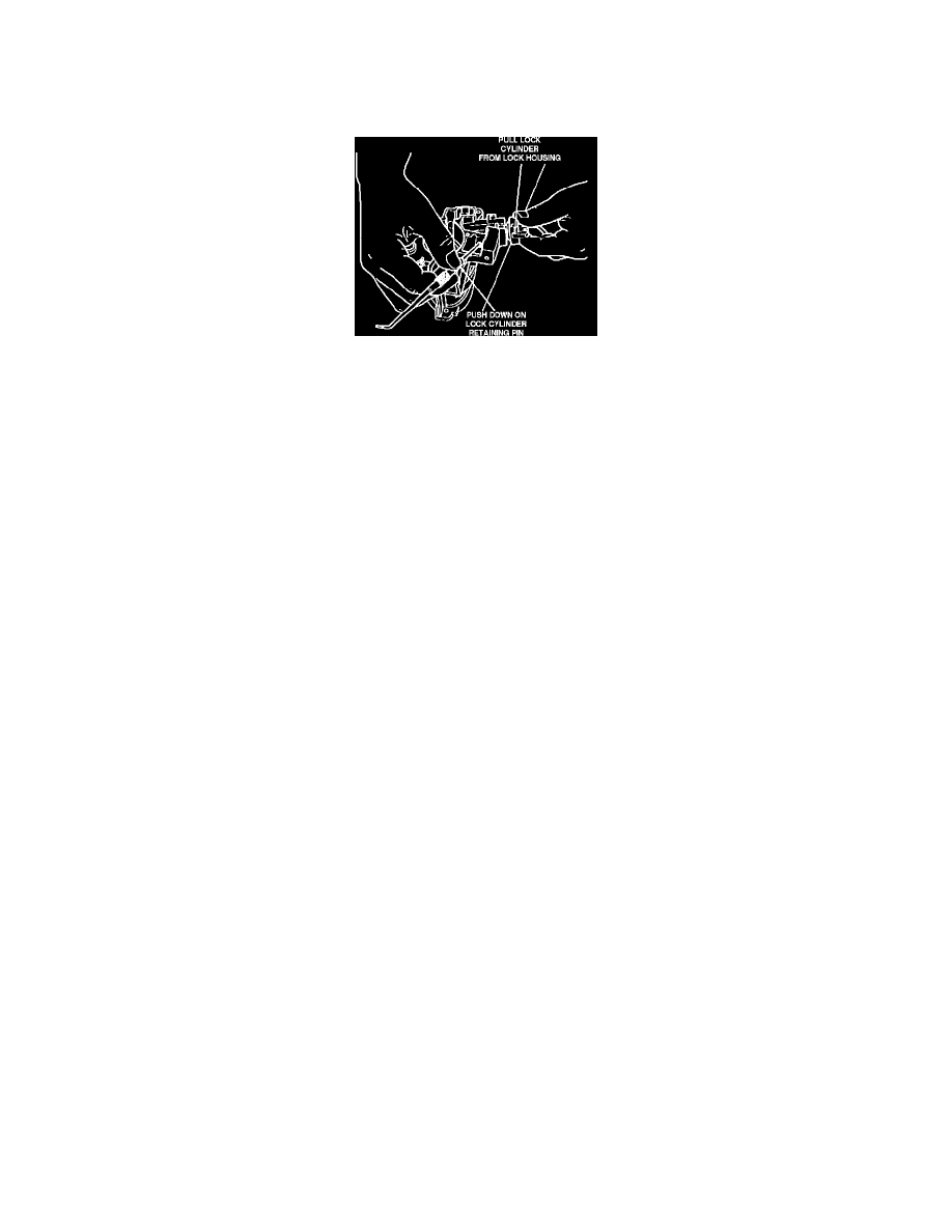
Fig. 4 Removing Ignition Lock Cylinder
REMOVAL
1.
Disconnect battery ground cable, then remove steering wheel as described below. Ensure steering wheel is in full up position on models with tilt
steering.
a.
Disconnect battery ground cable (two ground cables on diesel engines).
b.
From underside of steering wheel, remove screws attaching horn pad to steering wheel spokes.
c.
Lift up steering wheel pad, then disconnect horn wires and electrical connectors from pad.
d.
Remove steering wheel attaching bolt and damper, if equipped.
e.
Remove steering wheel using steering wheel remover T67L-3600-A or equivalent, Do not use a knock-off type wheel puller or strike end
of steering shaft, as damage will result.
2.
On models with tilt steering, remove tilt lever, then the steering column collar by pressing on collar from top and bottom while removing.
3.
On all models, remove lower dash panel trim cover, then the column shroud retaining screws from bottom of column shroud.
4.
Remove bottom half of shroud by pulling shroud down and toward rear of vehicle. Move shift lever as required to ease shroud removal on
models with automatic transmission.
5.
Lift top half of shroud from column.
6.
Turn lock cylinder with key to ON position. Selector lever must be placed in PARK position on vehicles with automatic transmission.
7.
Push down on lock cylinder retaining pin using a 1/8 inch diameter wire pin or small punch, then pull lock cylinder from column housing, Fig. 4.
8.
Disconnect lock cylinder electrical connector from horn brush electrical connector.
INSTALLATION
1.
Lubricate lock cylinder with suitable grease, then turn lock cylinder to ON position and depress retaining pin.
2.
Insert lock cylinder into housing in flange casting, ensuring that tab at end of cylinder aligns with slot in ignition drive gear.
3.
Turn key to OFF position, allowing cylinder retaining pin to extend into cylinder casting housing hole.
4.
Rotate lock cylinder to all positions, ensuring cylinder is operating properly.
5.
Connect lock cylinder electrical connector to horn brush electrical connector.
6.
Position top half of steering column shroud onto column so that screw moldings on shroud seat in mounting bores in column. Place shift lever in
lowest position to aid assembly on vehicles with automatic transmission.
7.
Install bottom half of shroud by sliding guides in bottom half of shroud into tabs in top half.
8.
Install shroud retaining screws and torque to 18.5-25.6 inch lbs.
9.
On models with tilt steering, install steering column collar by pressing on top and bottom while installing on column.
10.
Install tilt lever and torque to 2.2-3.6 ft. lbs.
11.
On all models, install steering wheel as follows:
a.
Position steering wheel on end of steering shaft, aligning mark and flats on steering wheel with mark and flats on steering shaft, and ensuring
that straight ahead steering wheel position corresponds with straight ahead position of front wheels.
b.
If equipped, install damper and align locators with hole in wheel hub.
c.
Install steering wheel attaching bolt and torque to 23-33 ft. lbs.
d.
Connect horn wires and electrical connectors, then install horn pad.
12.
Install lower dash panel trim cover, then connect battery ground cable.
13.
Check for proper start in P and N, and ensure that vehicle cannot be started in D or R positions and steering wheel locks in LOCK position.