
Ranger 2WD V6-245 4.0L VIN X SFI (1997)
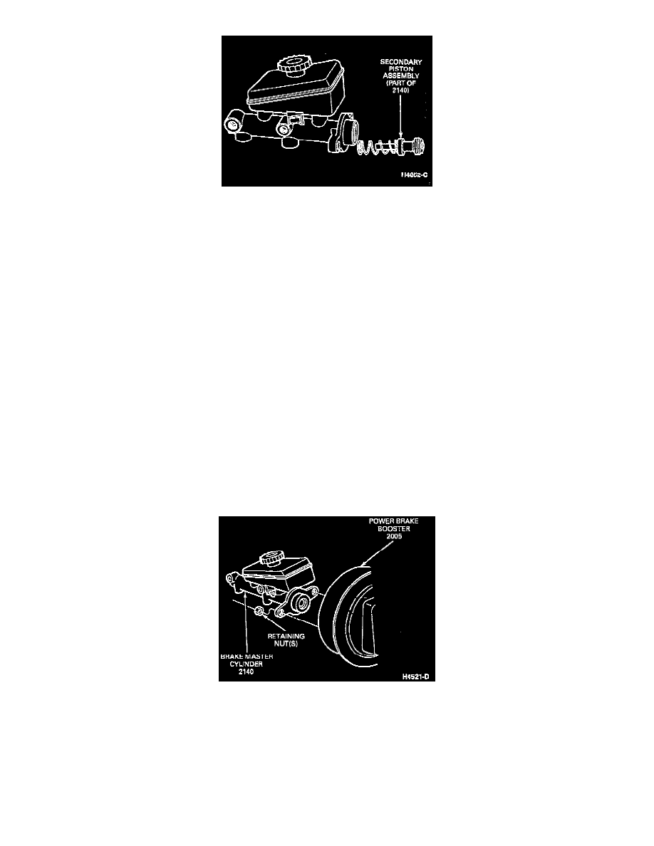
Secondary Piston Assembly
4. Remove the secondary piston assembly by directing compressed air into the outlet port at the blind end of the bore while plugging the other port.
Inspect for seal damage or twisting. Discard assembly.
WARNING: Do not attempt to hone a master cylinder bore if damage is found. If bore is found to be in good condition, check with your
ford dealer for availability of service repair kits. If none are available, brake master cylinder must be replaced.
5. Inspect the master cylinder bore for signs of etching, pitting, scoring or other damage.
ASSEMBLY
1. Clean the master cylinder body with clean isopropyl alcohol to remove any contamination.
2. Dip the repair kit piston assemblies in clean brake fluid High Performance DOT 3 Brake Fluid C6AZ-19542-AB or equivalent DOT 3 fluid
meeting Ford specification ESA-M6C25-A, DOT 3 to lubricate seals.
3. Carefully insert the complete secondary piston assembly in the master cylinder bore.
4. Carefully insert the primary piston assembly in the master cylinder bore.
5. Depress the primary piston and install the snap ring in the cylinder bore groove.
6. Install the cap and diaphragm on the brake master cylinder reservoir.
Removal and Installation
REMOVAL
1. Disconnect the brake warning lamp indicator wire from the plastic reservoir low fluid level warning-switch socket.
2. With the engine turned off, push the brake pedal down to expel vacuum from the power brake booster.
3. Disconnect the front brake tube and rear brake tube from the brake master cylinder.
4. Remove the wraparound clip and attaching nut from the booster master cylinder mounting stud.
Brake Master Cylinder
5. Remove the brake booster-to-master cylinder retaining nuts. Remove the brake master cylinder from the Dower brake booster.
NOTE: Before installing the brake master cylinder, check the distance from the outer end of the booster assembly push rod to the front face of the
power brake booster. Turn the push rod adjustment screw in or out as required to obtain a length of 24.89-25.27 mm (0.980-0.995 inch). Fabricate a
gauge block using dimensions shown in the following illustration.