
Ranger 2WD V6-245 4.0L VIN X SFI (1997)
CAUTION: For resistance checks, be sure that the tester selector switch is set to the TR SENSOR TEST position or damage to the ohmmeter
may result.
Disconnecting the Tester
1. Disconnect transmission tester from the DTR sensor connector.
CAUTION: Do not attempt to pry off connectors with a screwdriver. This will damage the connector and could result in a transmission concern.
2. Reinstall vehicle wiring harness. Verify connection by pulling up on the harness.
3. Reinstall all heat shields that were previously removed.
4. Disconnect transmission tester power lead from vehicle.
5. Erase all DTCs.
6. Rerun On-Board Diagnostic Tests to receive a pass code.
7. Verify that the customer concern has been eliminated.
Sensor Tests
CAUTION: Be sure that the DIGITAL 12 pin sensor cable connector (black) is used. If the wrong connection is made or the slide switch is in the
wrong position, the LEDs on the TR cable will give false or no response during testing. This will cause the replacement of good parts.
1. Place transmission range selector lever into PARK.
2. Ensure that the "E" cable ANALOG/DIGITAL switch is set to DIGITAL.
3. Move the transmission range selector lever through all ranges.
4. Monitor the LEDs, located on the "E" cable, in each gear position. The LED should illuminate RED for the appropriate range selected.
5. If the LED for the applicable gear range position fails to illuminate RED or if it lights for a position other than the gear selected:
^
Verify test cable connections at sensor and tester.
^
Verify transmission shift linkage for proper adjustment.
^
Verify DTR sensor for proper adjustment.
^
Retest.
6. If the sensor still fails to illuminate the LED RED for the selected gear range or indicates incorrect gear position, replace it.
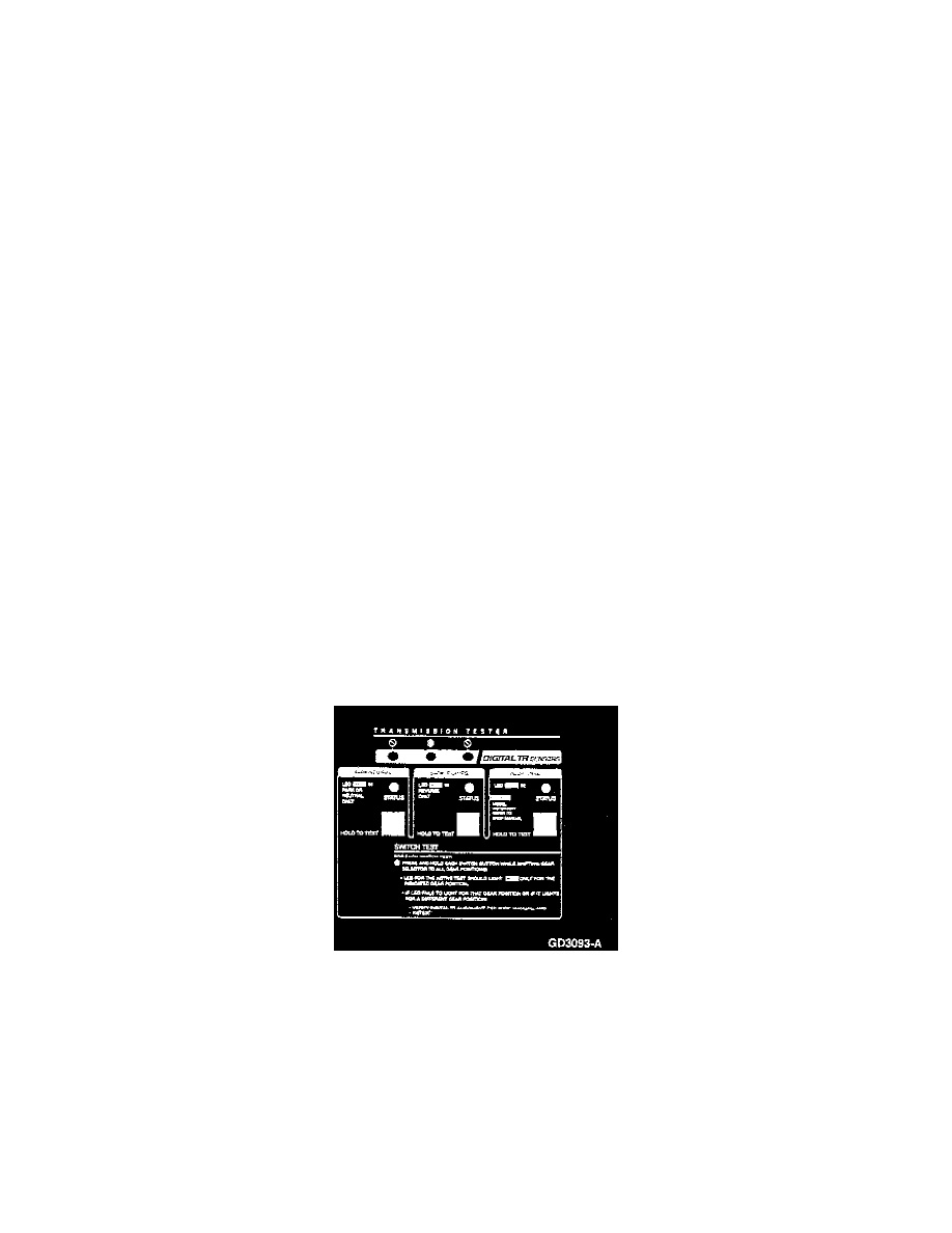
Switch Tests - Park/Neutral, Backup Lamp and Optional Circuits
NOTE:
^
LED lights red when circuit is closed.
^
LED turns off when circuit is open.
1. Press and hold each test button while moving the transmission range selector lever to each gear position.
2. Monitor each STATUS LED:
The LED in the appropriate gear position being testing should light red.
If the LED for the applicable gear position fails to light red, or if it lights for a position other than the gear selected:
^
Verify DTR alignment.
^
Retest.
3. If the DTR sensor fails, replace it.
After testing is finished, disconnect the tester.