
Ranger 2WD V6-245 4.0L VIN X SFI (1997)
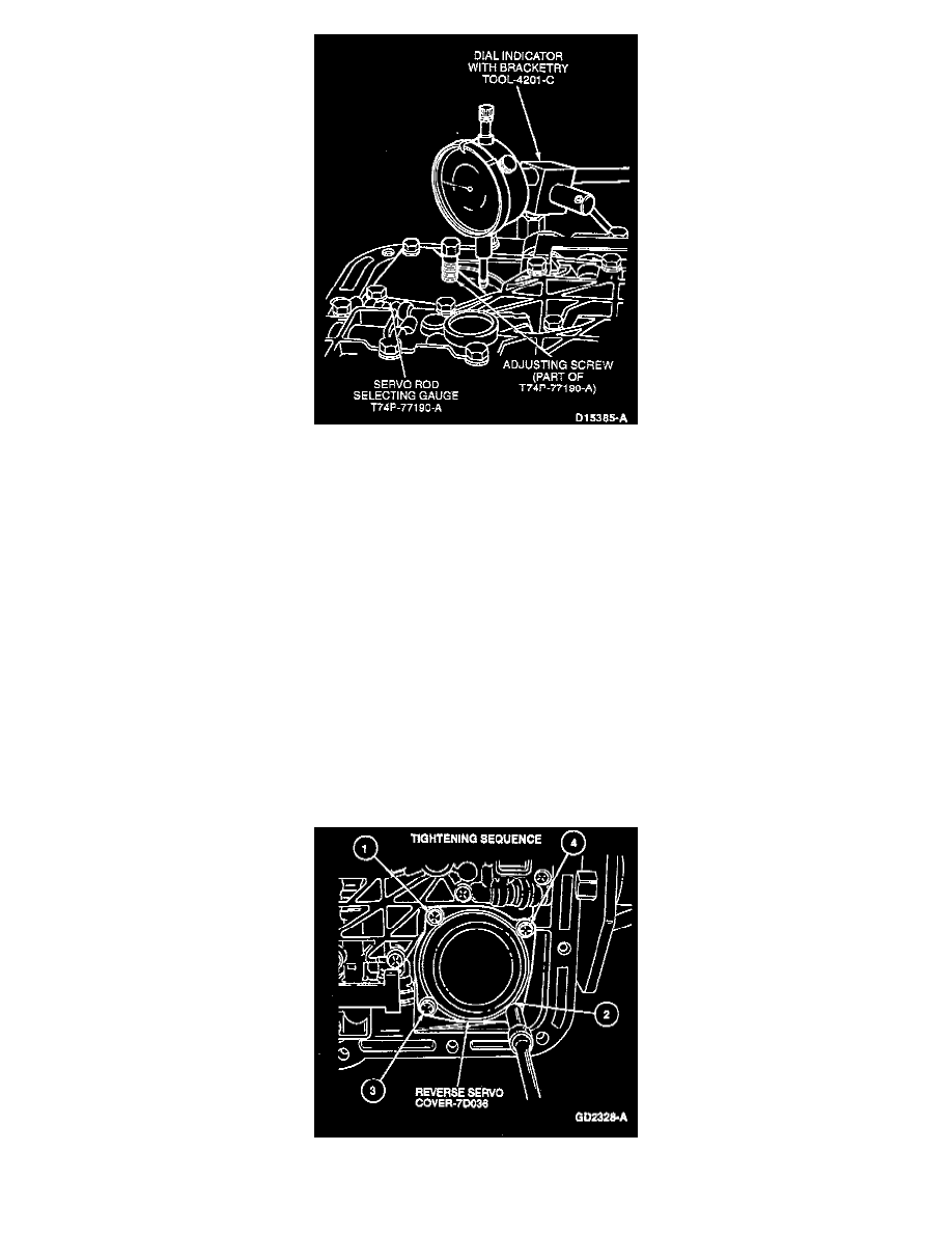
4. Install Dial Indicator with Bracketry TOOL-4201-C or equivalent on the transmission case. Position the indicator on the piston pad. Set the dial
indicator to zero.
5. Back out the servo gauge adjusting screw until it bottoms out on the tool. Record the distance the servo piston traveled.
NOTE: If the piston travel in this step is 3-5.6 mm (0.120-0.220 inch), it is within specification. If the piston travel is greater than 5.6 mm (0.220
inch), use the next longer piston and rod. If the piston travel is less than 3 mm (0.120 inch), use the next shorter piston and rod.
6. Use the above procedure to check the piston travel with the newly selected reverse band servo piston and rod (if required) to make sure that the
piston travel is 3-5.6 mm (0.120-0.220 inch).
Remove the servo gauge and the reverse band servo return spring.
54/53 mm (2.112/2.085 inches) I.D. - 1 Groove
51/50 mm (2.014/1.986 inches) I.D. - No Groove
49/48 mm (1.915/1.888 inches) I.D. - 2 Grooves
CAUTION: Make sure the test spring is removed after this step.
NOTE: Grooves are located on reverse servo rod.
7. Install the low/reverse servo and rod assembly into the case.
8. Install the low/reverse servo cover, new gasket and the four low/reverse servo cover-to-case screws. Tighten cover-to-case screws in sequence as
shown to 12-14 Nm (106-124 inch lbs.).