
Ranger 2WD V6-245 4.0L VIN X SFI (1997)
Drive/Propeller Shaft: Service and Repair
Replacement
Regular Cab
REMOVAL
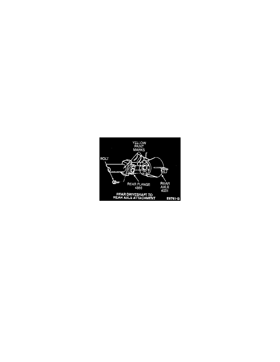
1. To maintain driveline balance, locate original paint mark on rear axle companion flange and mark driveshaft flange yoke in the same location. If
original mark is not visible on rear axle companion flange, mark both the rear axle companion flange and driveshaft flange yoke at any location.
NOTE: All driveshafts are balanced. Mark the driveshaft in relation to the rear universal joint yoke and the rear axle circular flange so that it may
be installed in the original position.
2. Remove the bolts retaining the driveshaft to the rear axle circular flange.
CAUTION: Do not allow driveshaft to hang free. Support the driveshaft during removal procedures.
3. Disconnect the driveshaft from the rear axle companion flange. Pull the driveshaft toward the rear of the vehicle until the driveshaft slip yoke
clears the extension housing and seal. Install the appropriate plug in the extension housing to prevent lubricant leakage.
INSTALLATION
1. Lubricate the driveshaft slip-yoke splines with Premium Long-Life grease XG-1-C or -K or equivalent meeting Ford specification ESA-M1C75-B.
Remove the plug from the transmission extension housing. Inspect the housing seal for damage; replace if required. Slide the driveshaft slip-yoke
into the output extension housing of the transmission. Do not allow the driveshaft slip-yoke to bottom out on the output shaft with excessive force.
2. Position the driveshaft so that the index mark on the rear yoke (or yellow dot on driveshaft tube) is in line with the index mark on the rear axle
companion flange. This ensures original driveline balance.
NOTE: When installing a new service driveshaft, align the factory-made yellow paint mark at the rear of the driveshaft tube with the
factory-made yellow paint mark on the rear axle companion flange.
3. Install the bolts that retain the driveshaft to the rear axle companion flange. Tighten the bolts to 95-129 Nm (70-95 ft. lbs.).
SuperCab
REMOVAL
1. To maintain driveline balance, locate original paint mark on the rear axle companion flange and mark driveshaft flange yoke in the same location.
If original mark is not visible on rear axle companion flange, mark both the rear axle companion flange and driveshaft flange yoke at any location.
NOTE: All driveshafts are balanced. Mark the driveshaft in relation to the rear universal joint yoke and the rear axle circular flange so that it may
be installed in the original position.
2. Remove the bolts that retain the driveshaft center bearing bracket to the frame crossmember. Remove spacers under the center bearing bracket, if
installed.
3. Remove the bolts retaining the driveshaft to the rear axle circular flange.
CAUTION: Do not allow driveshaft to hang free. Support the driveshaft during removal procedures.
4. Disconnect the driveshaft from the rear axle companion flange. Pull the driveshaft toward the rear of the vehicle until the driveshaft slip yoke
clears the extension housing and seal. Install the appropriate plug in the extension housing to prevent lubricant leakage.
INSTALLATION
1. Lubricate the driveshaft slip-yoke splines with Premium Long-Life Grease XG-1-C or -K or equivalent meeting Ford specification