
Ranger 2WD V6-3.0L VIN V Flex Fuel (2001)
^
Remove red locking wedge from face of connector
^
Remove each pin individually and clean accordingly
NOTE:
IF PINS ARE DAMAGED BEYOND THE ABILITY TO CLEAN, OBTAIN NEW PINS FOR REPAIR. ALL PINS WILL REQUIRE
SOLDERING TO WIRE FOR MORE ROBUST CONNECTION. REFERENCE APPROPRIATE PINS:
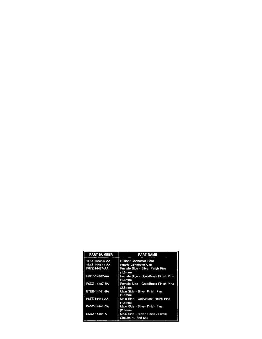
F67Z-14487-AA replacing silver finish pins (1.6 mm) and/or E6DZ-14487-AA replacing gold/brass finish pins (1.6 mm) and/or F6DZ-14487-BA
replacing gold/brass finish pins (2.8 mm).
^
When all pins are cleaned or replaced, install new Cap (1L5Z-14A541-AA) over existing connector 14A464
^
Insert all pins through new Rubber Boot (1L5Z-14A099-AA)
^
Install pins into existing connector (refer to the appropriate Electrical and Vacuum Troubleshooting Manual (EVTM) for correct pin positions)
^
Install existing red locking wedge and seat rubber boot to new cap
^
Insert connector into sheet metal (floor pan area)
OUTSIDE CAB UNDERNEATH VEHICLE/DRIVER'S SIDE
^
Remove cap from back of connector C309M (2000 model year) or C340M (2001 model year)
M = Male Side Of Connector
^
Remove white locking wedge from face of connector
^
Remove each pin individually, clean accordingly, and re-insert into correct cavity of lower connector 14A624 (refer to EVTM for correct pin
position)
NOTE:
IF PINS ARE DAMAGED BEYOND THE ABILITY TO CLEAN, OBTAIN NEW PINS FOR REPAIR. ALL PINS WILL REQUIRE
SOLDERING TO WIRE FOR MORE ROBUST CONNECTION. REFERENCE APPROPRIATE PINS:
E7EB-14461-BA replacing silver finish pins (1.6 mm) and/or F6TZ-14461-AA replacing gold/brass finish pins (1.6mm) and/or F6DZ-14461-CA
replacing silver finish pins (2.8 mm) and/or E5DZ-14461-A replacing silver finish (1.6 mm Circuits 52 and 64)
^
Install existing white locking wedge and reseat existing cap to back of connector C309M (2000 model year) or C340M (2001 model year)
^
Apply dielectric grease sparingly to all pins
^
Slide sleeve over upper connector and lock-in place
^
Slide lower connector over sleeve and secure with bolt in connector - torque bolt to 4.8 +/- 0.8 Nm (42.5 +/- 7 lb-in)
After connector has been reinstalled, verify concern has been eliminated. Reinstall carpet or vinyl lining, door scuff plate, and driver's seat.