
Ranger 2WD V6-3.0L VIN V Flex Fuel (2001)
3.
Remove and discard the band lock nut, then back out the adjusting screw three to four turns.
4.
Install special service tool 307-340 (T95L-77028-A).
5.
Tighten special tool to compress the servo spring.
CAUTION
THE SERVO COVER IS UNDER SPRING TENSION.
6.
Remove the Servo Cover retaining ring.
7.
Slowly remove the tension on the J-hook nut and remove the Servo Cover compressor.
NOTE
DO NOT ALLOW THE PISTON TO COME OUT OF THE BORE.
8.
Tap lightly on the cover, then remove the cover.
NOTE
DO NOT DAMAGE THE COVER SEALS DURING INSTALLATION. DO NOT PRESS SERVO COVER AND SEALS PAST THE RELIEF
HOLE IN THE CASE OR SEALS MAY BE DAMAGED.
9.
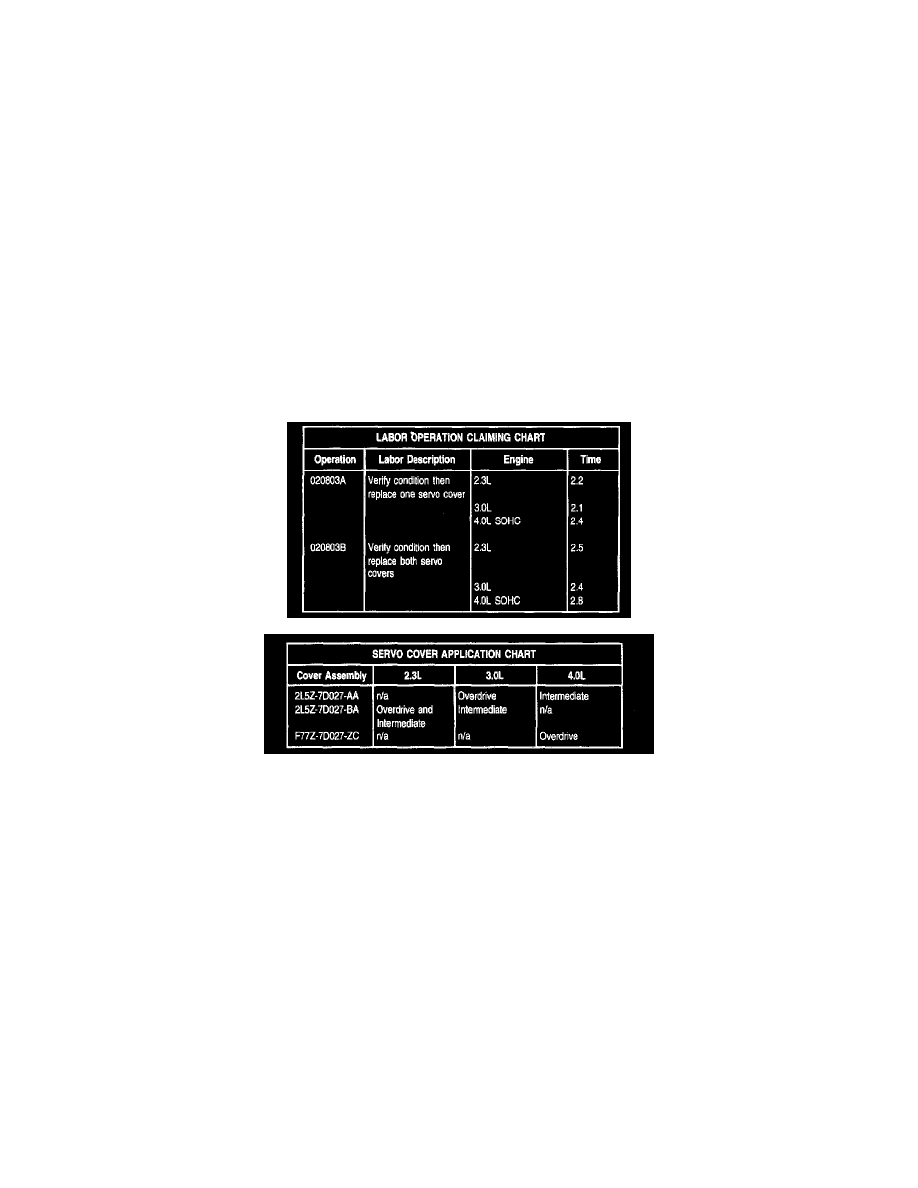
Lubricate Servo Cover Seal and install a new Servo Cover Assembly onto the piston and into the piston bore Refer to the Servo Cover Application
Chart for Servo Cover applications.
10.
Install special service tool 307-340 (T95L-77028-A).
11.
Tighten special tool to compress the Servo Cover and spring.
12.
Install retaining ring.
13.
Slowly remove the tension on the J-hook nut and remove the Servo Cover compressor. Clean residual fluid from Servo Cover area.
NOTE
INSTALL, BUT DO NOT TIGHTEN, A NEW LOCK NUT ON THE SCREW.
NOTE
THE WRENCH WILL CLICK AT THE SPECIFIED TORQUE.
NOTE
IF REPLACING BOTH SERVO COVERS, ORDER TWO (2) NEW LOCK NUTS.
14.
Apply petroleum jelly to the lock nut seal. Install new locknut, but do not tighten at this time. Using special service tool 307-S022, tighten the
band adjusting screw to 14 N.m (10 Lb-ft), then back oft the adjusting screw exactly two (2) turns and hold that position.