
Ranger 2WD V6-4.0L (2010)
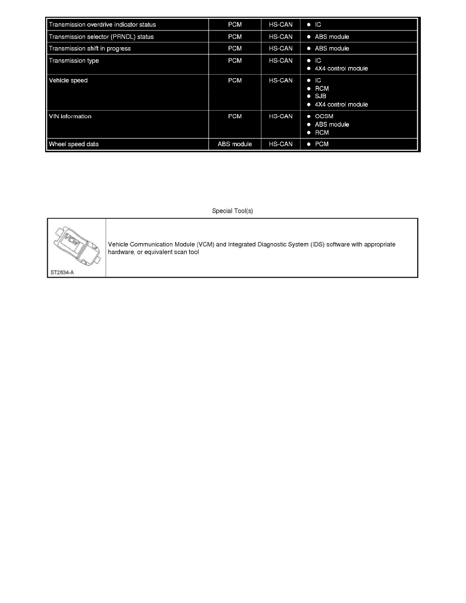
Special Tool(s) Used With Diagnostics
Module Configuration
Inspection and Verification
Module Configuration
Inspection and Verification
This provides step-by-step module configuration procedures. Carry out Programmable Module Installation (PMI) when another diagnostic/repair
information directs to carry out configuration or when DTCs from the chart are present. See: Service and Repair
Principles of Operation
Module Configuration
Principles of Operation
NOTE: The Smart Junction Box (SJB) is also known as the Generic Electronic Module (GEM).
Configurable modules accommodate a variety of vehicle options, eliminating the need for many unique modules for one vehicle line. These modules
must be configured when replaced as part of a repair procedure. Configurable modules should not be exchanged between vehicles since the settings are
unique to each vehicle. Failure to configure a new module may result in incorrect operation and/or DTCs setting.
The following are the 3 different methods of configuration:
-
Programmable Module Installation (PMI)
-
Module reprogramming ("flashing")
-
Programmable parameters
Some modules do not support all 3 methods.
Definition of Terms
The following are definitions of configuration terms:
Programmable Module Installation (PMI)