
Ranger 2WD V6-4.0L (2010)
If not OK, REFER to the Wiring Diagrams to identify the possible causes of the circuit short. CLEAR the DTCs. REPEAT the network test with the scan
tool. See: Diagrams/Electrical Diagrams/Diagrams By Number
-------------------------------------------------
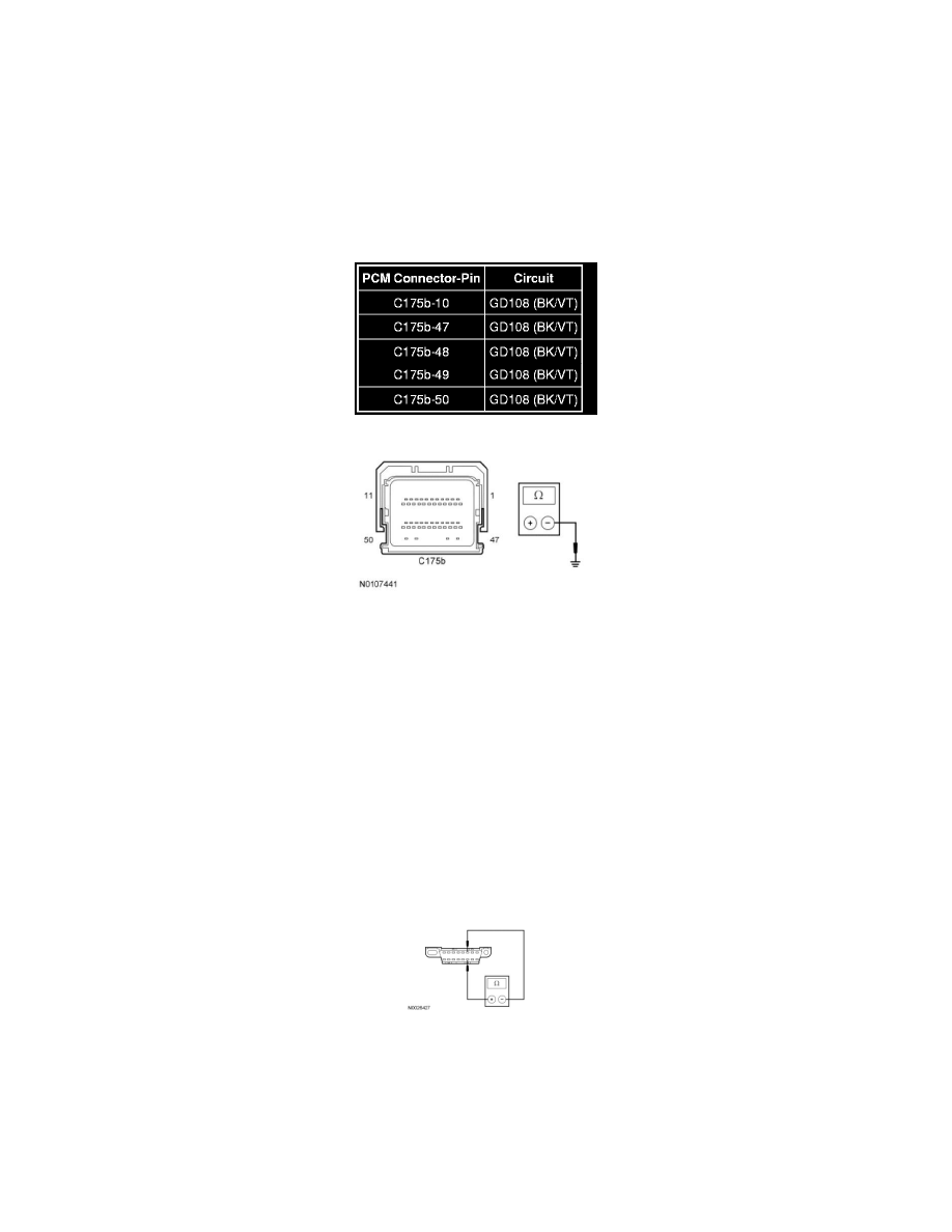
A4 CHECK THE PCM GROUND CIRCUITS FOR AN OPEN
-
Ignition OFF.
-
Disconnect: Negative Battery Cable.
-
Measure the resistance between the PCM, harness side and ground as follows:
-
Are the resistances less than 5 ohms?
Yes
GO to A5.
No
REPAIR the circuit. CONNECT the negative battery cable. CLEAR the DTCs. REPEAT the network test with the scan tool.
-------------------------------------------------
A5 CHECK THE HS-CAN TERMINATION RESISTANCE
-
Measure the resistance between the DLC C251-6, circuit VDB04 (WH/BU), harness side and the DLC C251-14, circuit VDB05 (WH), harness
side.
-
Is the resistance between 54 and 66 ohms?
Yes
CONNECT the negative battery cable. GO to A7.
No
GO to A6.