
Ranger 2WD V6-4.0L (2010)
-------------------------------------------------
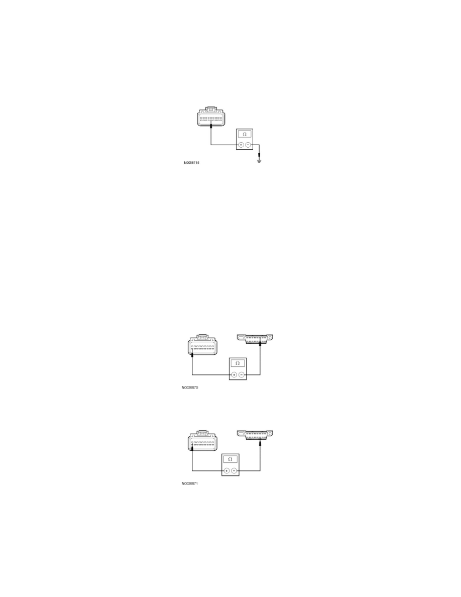
B2 CHECK THE GROUND CIRCUIT FOR AN OPEN
-
Ignition OFF.
-
Disconnect: Negative Battery Cable.
-
Measure the resistance between the OCSM C3159-14, circuit GD174 (BK/WH), harness side and ground.
-
Is the resistance less than 5 ohms?
Yes
GO to B3.
No
REPAIR the circuit. CONNECT the negative battery cable. CLEAR the DTCs. REPEAT the network test with the scan tool.
-------------------------------------------------
B3 CHECK THE HS-CAN CIRCUITS BETWEEN THE OCSM AND THE DLC FOR AN OPEN
-
Measure the resistance between the OCSM C3159-18, circuit VDB04 (WH/BU), harness side and the Data Link Connector (DLC) C251-6, circuit
VDB04 (WH/BU), harness side.
-
Measure the resistance between the OCSM C3159-9, circuit VDB05 (WH), harness side and the DLC C251-14, circuit VDB05 (WH), harness
side.
-
Are the resistances less than 5 ohms?
Yes
CONNECT the negative battery cable. GO to B4.
No
REPAIR the circuit in question. CONNECT the negative battery cable. CLEAR the DTCs. REPEAT the network test with the scan tool.