
Ranger 2WD V6-4.0L (2010)
-
Are the voltages greater than 10 volts?
Yes
GO to G3.
No
VERIFY the Battery Junction Box (BJB) fuses 17 (40A) and 33 (30A) and the SJB fuse 20 (10A) are OK.
If OK, REPAIR the circuit in question.
If not OK, REFER to the Wiring Diagrams to identify the possible causes of the circuit short. CLEAR the DTCs. REPEAT the network test with the scan
tool. See: Diagrams/Electrical Diagrams/Diagrams By Number
-------------------------------------------------
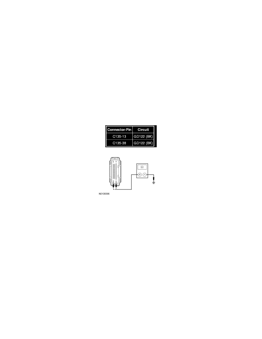
G3 CHECK THE ABS MODULE GROUND CIRCUITS FOR AN OPEN
-
Ignition OFF.
-
Disconnect: Negative Battery Cable.
-
Measure the resistance between the ABS module, harness side and ground as follows:
-
Are the resistances less than 5 ohms?
Yes
GO to G4.
No
REPAIR the circuit. CONNECT the negative battery cable. CLEAR the DTCs. REPEAT the network test with the scan tool.
-------------------------------------------------
G4 CHECK THE HS-CAN CIRCUITS BETWEEN THE ABS MODULE AND THE DLC FOR AN OPEN
NOTE: The ABS module must be disconnected for this test step to be accurate.
-
Measure the resistance between the ABS module C135-26, circuit VDB04 (WH/BU), harness side and the DLC C251-6, circuit VDB04
(WH/BU), harness side.