
Ranger 2WD V6-4.0L (2010)
-
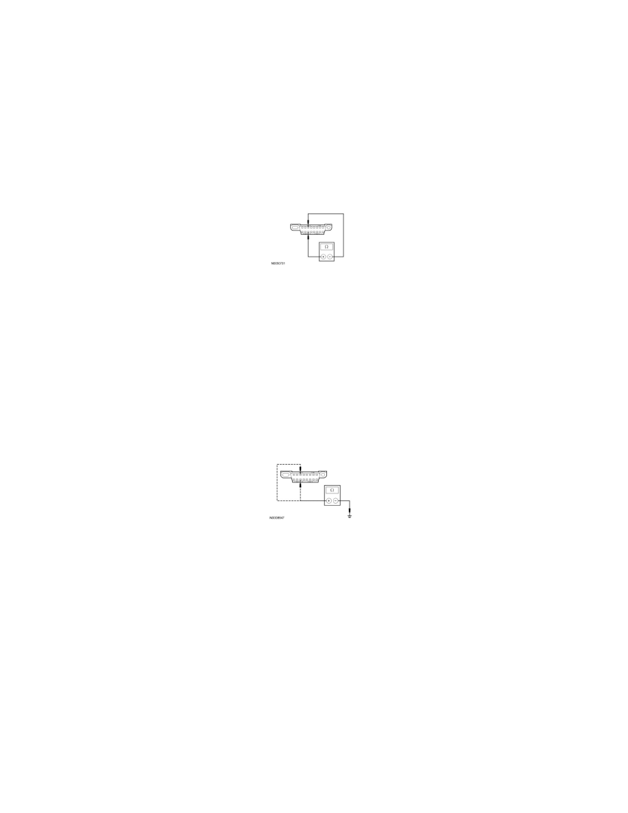
Is the resistance between 108 and 132 ohms?
Yes
GO to J9.
No
GO to J4.
-------------------------------------------------
J4 CHECK THE MS-CAN (+) AND MS-CAN (-) CIRCUITS FOR A SHORT TOGETHER
-
Measure the resistance between the DLC C251-3, circuit VDB06 (GY/OG), harness side and the DLC C251-11, circuit VDB07 (VT/OG), harness
side.
-
Is the resistance less than 5 ohms?
Yes
GO to J10.
No
GO to J9.
-------------------------------------------------
J5 CHECK THE MS-CAN (+) AND MS-CAN (-) CIRCUITS FOR A SHORT TO GROUND
-
Measure the resistance between the DLC C251-3, circuit VDB06 (GY/OG), harness side and ground; and between the DLC C251-11, circuit
VDB07 (VT/OG), harness side and ground.
-
Are the resistances greater than 5,000 ohms?
Yes
GO to J6.
No
GO to J12.
-------------------------------------------------
J6 CHECK THE MS-CAN (+) AND MS-CAN (-) CIRCUITS FOR A SHORT TO VOLTAGE
-
Connect the vehicle battery.
-
Ignition ON.
-
Measure the voltage between the DLC C251-3, circuit VDB06 (GY/OG), harness side and ground; and between the DLC C251-11, circuit VDB07
(VT/OG), harness side and ground.