
Ranger 4WD L4-140 2.3L SOHC (1984)
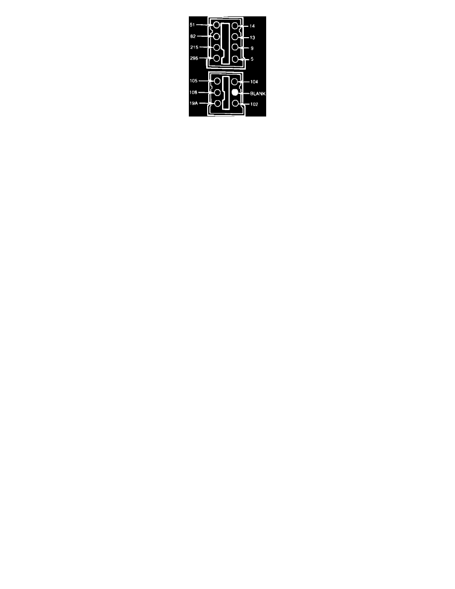
Fig. 6 Graphic display warning system electrical connectors. 1984-87 Bronco ll & Ranger
TROUBLESHOOTING
The following precautions must be taken when performing any diagnosis:
1.
Check condition of system fuse before proceeding.
2.
All tests must be performed with ignition switch in Run position.
3.
Ambient temperature must be 60---80°F to provide accurate test results.
4.
All voltage measurements must be made using a suitable digital voltmeter. Do not touch voltmeter probes with fingers.
5.
Refer to system wiring diagram, Figs. 4 and 5, when performing tests. The harness connectors, Fig. 6, are located at front of console.
Taillight LED Illuminates or Gives False Indication
1.
Measure voltage between terminals 14 and 102 with ignition switch in Run position and headlight switch On.
2.
Voltage should measure .48 volt or more.
3.
If voltage is not within specifications, check condition of bulbs and replace as necessary. If bulbs are satisfactory, check circuits for an open or
short and repair as necessary.
4.
If voltage is within specifications, but taillight LED remains lit, replace graphic display module.
Headlight LED Illuminates Or Gives False Indication
1.
Measure voltage between terminals 13 and 108 with ignition switch in Run position and headlight switch On.
2.
Voltage should measure .47 volt or more.
3.
If voltage is not within specifications, check condition of bulbs and replace as necessary. If bulbs are satisfactory, check circuits for an open or
short and repair as necessary.
4.
If voltage is within specifications, but headlight LED remains lit, replace graphic display module.
Brake Light LED Illuminates Or Gives False Indication
1.
Measure voltage between terminals 9 and 104 with ignition switch in Run position.
2.
Voltage should measure .19 volt or more.
3.
If voltage is not within specifications, check condition of left brake light bulb and replace as necessary. If bulb is satisfactory, check circuits for an
open or short and repair as necessary.
4.
If voltage is within specifications, but brake light LED remains lit, proceed to step 5.
5.
Measure voltage between terminals 5 and 105 with ignition switch in Run system electrical connectors. 1984---85 Bronco II & Ranger position.
6.
Voltage should measure .19 volt or more.
7.
If voltage is not within specifications, check condition of right brake light bulb and replace as necessary. If bulb is satisfactory, check circuits for
an open or short and repair as necessary.
8.
If voltage is within specifications, but brake light LED remains lit, replace graphic display module.
Low Fuel LED Illuminates or Gives False Indication
1.
Measure voltage between terminals 57 and 215 with ignition switch in Accessory or Run position and fuel level low enough to illuminate LED.
2.
Voltage should be 10.5---13.5 volts.
3.
If voltage is not within specifications, check circuits for an open or short and repair as necessary.
Washer Fluid LED Illuminates Or Gives False Indication
1.
Measure voltage between terminals 82 and 57 with ignition switch in Accessory or Run position and washer fluid level low enough to illuminate
LED.
2.
Voltage should be 10.5---13.5 volts.
3.
If voltage is not within specifications, check circuits for an open or short and repair as necessary.
No LEDs Will Illuminate
1.
Measure voltage between terminals 57 and 296 with ignition switch in Accessory or Run position.
2.
Voltage should be 10.5---13.5 volts.
3.
If voltage is not within specifications, check circuits for an open or short and repair as necessary.
One Or More LEDs Will Not Illuminate
1.
Replace defective LED indicator(s) located in console.