
Ranger 4WD L4-140 2.3L SOHC (1984)
Alignment: Service and Repair
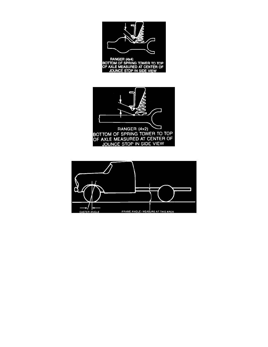
Fig. 5 Front Ride Height. 4x4 Models
Fig. 5 Ride height measurement at front end. 4 X 4 models
Fig. 7 Frame Ride Height
Front wheel alignment specifications and method of checking caster, camber and toe-in for Twin I-beam front axles on 4 x 2 models or independent
front suspension on 4 x 4 models is determined with truck at normal operating height, provided front ride height is within specifications, and tires are
inflated to specified cold pressure.
To determine riding height, measure distance between bottom of spring tower and top of axle, Figs. 4 and 5. Refer to ``Wheel Alignment
Specifications Chart'' to determine alignment specifications for the particular riding height of truck. If riding height does not fall within specifications, it
should be corrected by installing proper springs or by use of shims.
Alignment equipment indicates a true reading only when frame is horizontal. Measure left and righthand angle as shown in Fig. 6. If frame is not level
(due to tire, spring or load differences), the caster angle reading must be modified to compensate for frame angles. If front is higher than rear, subtract
amount of angle from reading. If front is lower than rear, add angle. Check frame angle with a protractor and take frame angle measurement on flat area
immediately adjacent to rear spring front hanger. Axles are not to be bent or twisted to correct caster or camber readings.