
Ranger 4WD L4-140 2.3L SOHC (1984)
on a capacitance bridge at 1 kHz at a maximum voltage of 35O mV rms.
The radio noise suppression capacitor is built into the rectifier assembly and cannot be serviced by itself. To test the capacitor, put the
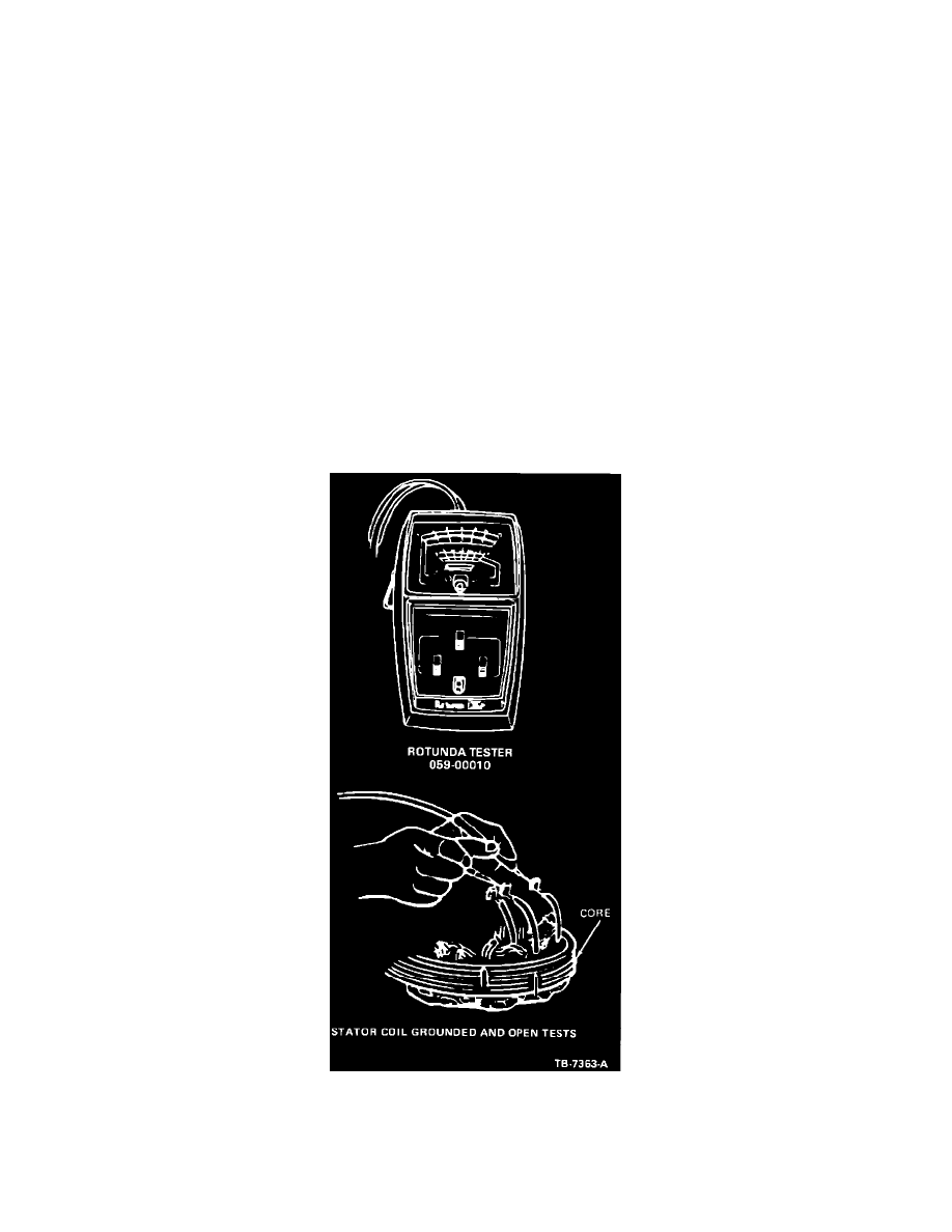
ohmmeter (Tool 059-00010 or equivalent) "Multiply By" setting at 1000 and zero the meter. Text values shown in brackets () are
referenced to Tool 059-00010 and may be different if another tester is used.
WARNING:
DIGITAL METERS CANNOT BE USED TO PERFORM THIS CAPACITOR TEST. THE RECTIFIER ASSEMBLY
MUST BE DRY.
1.
Contact one probe to one of the rectifier assembly B+ blade terminals and contact the other probe to the rectifier assembly
base plate. Reverse the probes and repeat the test. One position should give an infinite reading, indicating the reverse current
direction through the diodes and the reverse position should give a reading of about (1000) ohms, indicating the forward
current direction. The same reading in both directions indicates a defective rectifier assembly.
2.
Contact the probes to the rectifier assembly B+ terminal and base plate in the forward current (1000) ohms reading direction.
While observing the meter indicator needle, reverse the probes and again contact them to the rectifier assembly B+ terminal
and base plate. The indicator needle should jump slightly (indicating that the ohmmeter batteries are charging the capacitor)
and then return to its original position (infinite reading).
If the needle does not jump, the capacitor is open. Replace the rectifier assembly.
Stator Coil Grounded Test
These tests are made to determine if the stator coil is operating properly. Remove the stator from the alternator and disconnect it
from the rectifier assembly (refer to DISASSEMBLY procedure). Put the ohmmeter "Multiply By" setting at 1000.
Figure 10
1.
Connect the ohmmeter probes to one of the stator leads and to the stator laminated core (Figure 10). Be sure that the probe
makes a good electrical connection with the stator core. The meter should show an infinite reading (no needle movement).
2.
If the meter does not indicate an infinite reading (needle moves), the stator winding is shorted to the core and the stator must