
Ranger 4WD L4-140 2.3L SOHC (1984)
9.
Wipe the heat transfer grease from the rectifier assembly base and rectifier mounting area of the rear housing with a clean cloth.
10.
Replace the brushes if they are worn shorter than 6.35 mm (1.4 inch).
11.
Remove the sealing compound from the brush pin hole in the regulator.
Assembly
1.
Install the bearing in the front housing. Press on the outer race only.
2.
Position the bearing retainer on the front housing and install the attaching screws. Tighten the screws to 2.8-4.8 N-m (25-40 in.lbs.).
3.
If the stop ring was removed from the rotor shaft, install a new ring by sliding it over the end of the shaft and into the groove. Do not open the ring
with snap ring pliers as permanent deformation of the ring will result.
4.
Install the rotor stop on the rotor shaft with the recessed side against the stop ring.
5.
Install the rotor in the front housing and clamp the housing in a vise equipped with protective jaws.
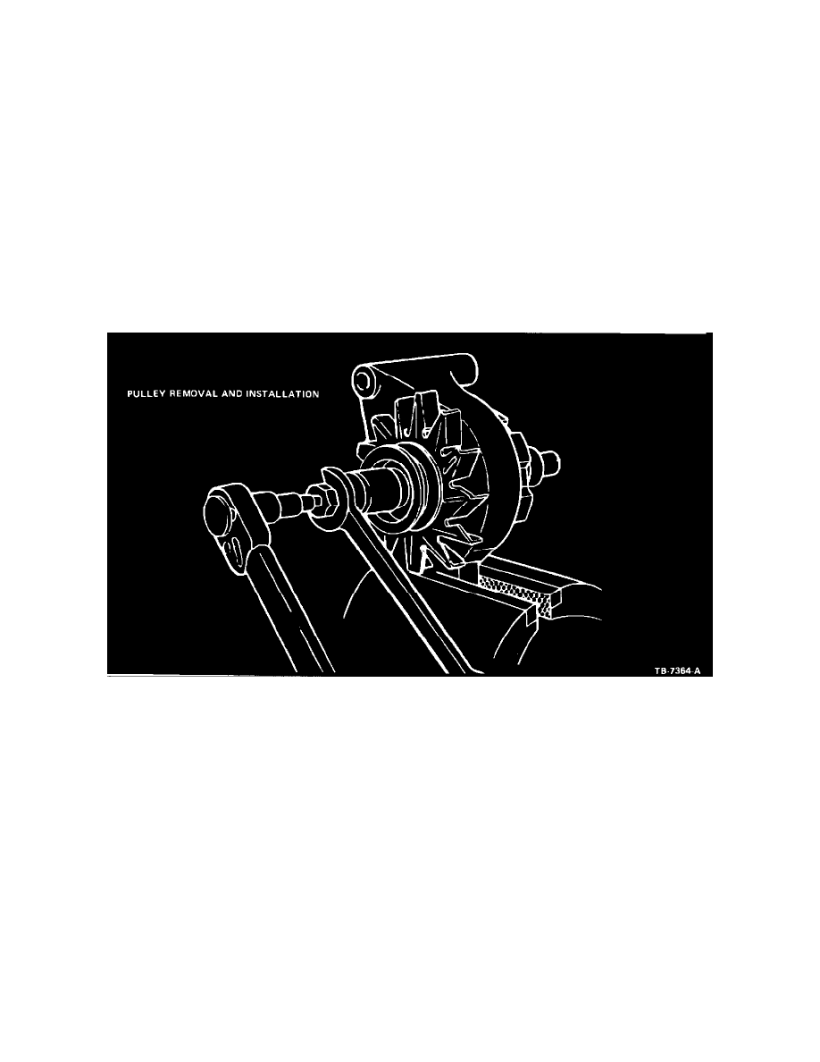
Figure 11
6.
Install the fan spacer, fan, drive pulley, flat washer and nut on the rotor shaft. Tighten the nut to 82- 135 N-m (60-100 ft.lbs.) using tool
T65P-10300-B or equivalent (Figure 11).
7.
Remove the rotor and housing assembly from the vise and check for free rotation of the rotor in the housing.
8.
Support the rear housing close to the bearing boss to prevent damage to the housing and install the bearing using a suitable arbor press. Press the
bearing into the bore until it is flush with the outside rear surface of the housing.
9.
Wipe the rectifier assembly base plate with a clean cloth. Apply a 2.0 mm (3/32 inch) wide by 20 mm (3/4 inch) long strip of ESF-M99G138-A
heat sink compound lengthwise across the rectifier assembly base plate.
10.
Wipe the rectifier mounting surface of the rear housing with a clean cloth and seat the rectifier into the recessed mounting area.
CAUTION: THE RECTIFIER ASSEMBLY IS COOLED BY CONDUCTION RECTIFIER HEAT DIRECTLY INTO THE HOUSING.
FAILURE TO REMOVE FOREIGN MATERIAL FROM THE MOUNTING SURFACES OR FAILURE TO APPLY HEAT SINK
COMPOUND MAY CAUSE RECTIFIER OVERHEATING.
11.
Install the four rectifier assembly attaching screws. Tighten the screws to 2.8-4.0 N-m (25-35 in.lbs.).
12.
Position the stator assembly in the rear housing and align the scribe marks made during disassembly. Push the three stator terminals onto the
rectifier blade terminals and solder securely using resin core electrical solder. Work quickly to prevent overheating the rectifier.