
Ranger 4WD L4-140 2.3L SOHC (1984)
Clutch Release Bearing: Service and Repair
1. Disconnect hydraulic clutch system master cylinder from clutch pedal.
2. Raise and support vehicle, then remove dust cover from clutch housing and disconnect hydraulic clutch linkage from housing and release lever.
Remove starter.
3. Remove clutch housing to engine block bolts, noting direction of bolt installation, then mark alignment of driveshaft and companion flange and
remove driveshaft.
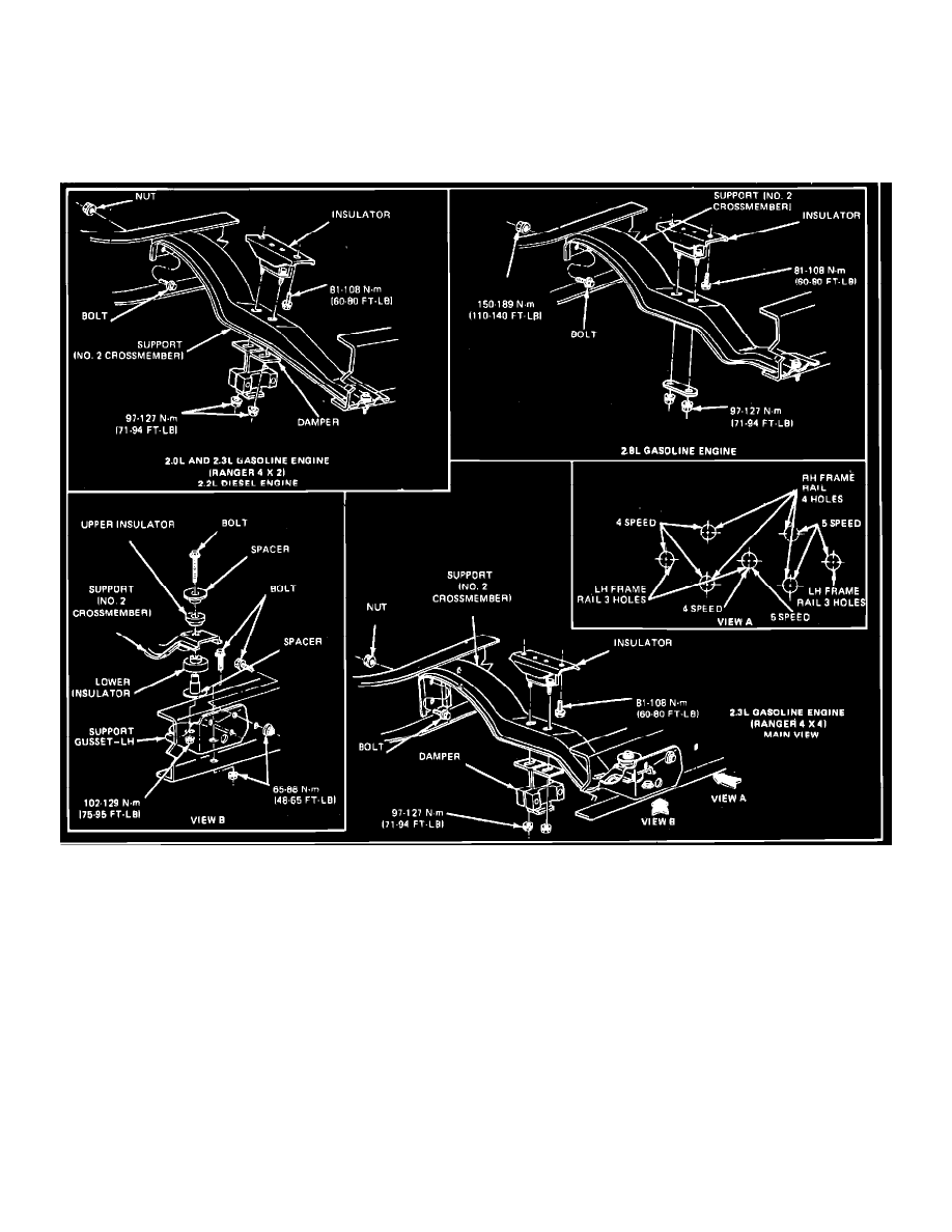
Fig. 1 Transmission rear support installation. 1983---84
4. Remove nuts which attach transmission and insulator to #2 crossmember support, then raise transmission with suitable jack and remove # 2
crossmember support. Lower transmission and clutch housing.
5. Remove release lever, and hub and bearing, then mark assembled position of pressure plate and cover to flywheel.
6. Loosen pressure plate and cover attaching bolts evenly until pressure plate springs are expanded, then remove bolts.
7. Remove pressure plate and cover assembly and clutch disc from flywheel.
8. Position clutch disc on flywheel so that tool D79T-7550-A or equivalent can enter clutch pilot bearing and align disc.
9. Align pressure plate and cover assembly to flywheel and position pressure plate and cover assembly on flywheel, aligning pressure plate and disc,
then install assembly to flywheel retaining bolts. Torque bolts to 15-24 ft lbs (20-32 Nm) and remove tool.
10. Position clutch release bearing and bearing hub on release lever and install release lever on release lever seat in flywheel housing, then coat release
lever fingers and lever pivot ball with suitable lubricant and fill annular groove of release bearing hub with grease.
11. Raise transmission and clutch housing into position and install # 2 crossmember support to frame, then install connecting nuts, bolts and washers
and torque to specifications.
12. Lower transmission and insulator into support, then install nuts and torque to 71-94 ft lbs (95-127 Nm). Remove transmission jack.
13. Install driveshaft, aligning marks on driveshaft and companion flange, and torque bolts to 70-95 ft lbs (94-128 Nm).
14. Install housing to engine block bolts in same direction as removed and torque to 28-38 ft lbs (37-51 Nm).
15. Install hydraulic clutch linkage on housing in position with release lever, dust shield, and starter, then lower vehicle and check clutch for proper