
Ranger 4WD L4-140 2.3L SOHC (1984)
Differential Case: Service and Repair
Ford Removable - Differential Case
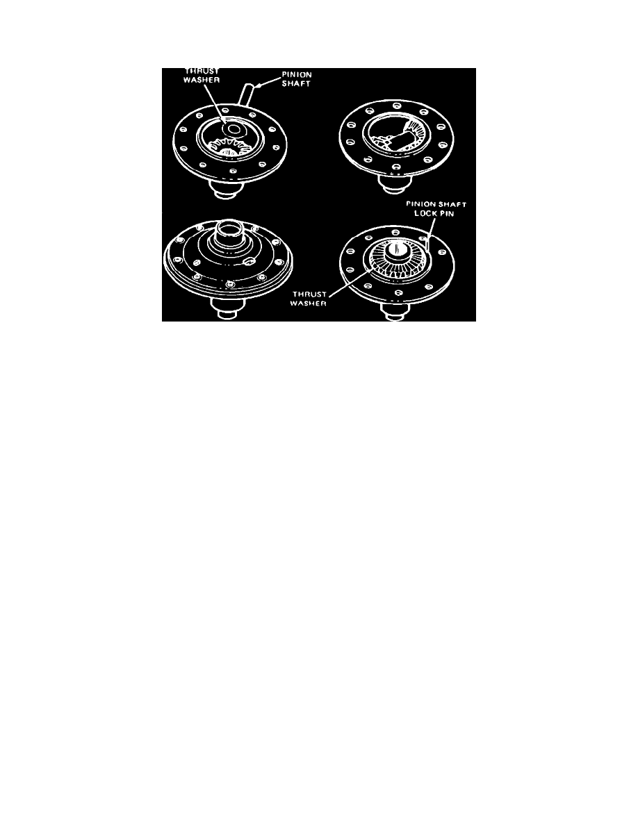
Fig. 10 Assembling differential case
Standard Differential
1.
Place side gear thrust washer and side gear in differential case bore, Fig. 10. Liberally lubricate all differential components with suitable
lubricant during assembly.
2.
Using soft faced hammer, drive differential pinion shaft into case only far enough to retain pinion thrust washer and pinion gear.
3.
Place second differential pinion and thrust washer in position and drive pinion shaft into place, carefully aligning pinion shaft lock pin holes.
4.
Place second side gear and thrust washer in position and install pinion shaft lock pin and the cover on differential case then insert axle shaft spline
in side gear spline to check for free rotation of differential gears.
5.
Using suitable solvent, clean tapped holes in ring gear.
6.
Insert two 7/16 N. F. bolts two inches long through differential case flange and thread them three or four turns into ring gear as a guide for aligning
ring gear bolts, then press or tap ring gear into position. If new bolts show a green or yellow coating of at least 1/2 inch on threaded area, use
as is. If bolts are not coated, apply small amount of suitable sealant to threads. Torque bolts to 70---80 ft. lbs. Never install used bolts.
7.
If differential bearings were removed, press them on using tool T57L-4221-A2 or equivalent.
8.
Wipe thin coating of suitable lubricant on carrier differential bearing bores, then place cups on bearings and set differential case assembly in
carrier.
9.
Assemble differential case and ring gear assembly in carrier so that marked tooth on drive pinion indexes between marked teeth on ring gear.
10.
Slide assembly along bores until a slight amount of backlash is felt between gear teeth.
11.
Set adjusting nuts in bores so that they just contact bearing cups, engaging nuts approximately the same number of threads on both sides.
12.
Carefully position differential bearing caps on carrier, matching alignment marks.
13.
Ensure that adjuster nuts are properly threaded in cap and carrier and that they turn freely, then install bearing caps and alternately torque them to
70---80 ft. lbs.
14.
If adjusting nuts do not turn freely as cap bolts are tightened, remove differential bearing caps and inspect for damaged threads or incorrectly
positioned caps.
15.
Adjust backlash and differential bearing preload.
Traction-Lok Differential
When new clutch plates are used, soak plates in suitable hypoid lubricant for approximately 30 minutes before installation. Lubricate all parts
with suitable hypoid lubricant during assembly.
1.
Mount differential case in suitable vise and place side gear thrust washer and side gear in counterbore of case.
2.
Install differential pinion thrust washers and place pinion gears on side gear, aligning holes in washers and gears with holes in case.
3.
Install center block so that shaft holes are aligned with holes in pinion gears and case.
4.
Using brass drift, drive in long differential pinion shaft from outside of case, aligning lock pin holes in shaft with lock pin holes in case.
5.
Position center block so that long shaft is driven through rough side and short shaft is driven through machined side.
6.
Using suitable drift, install shaft lock pins, ensuring that differential pinion and side gears move freely.
7.
Place four preload pins in holes provided in center block.
8.
Position preload plate over four springs, ensuring that springs are properly seated. The preload plate straddles the center block over its narrower
machined width.