
Ranger 4WD L4-140 2.3L VIN A EFI (1997)
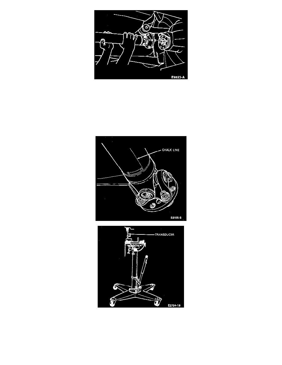
3. Disconnect the driveshaft from the rear axle companion flange. Rotate the driveshaft 180 degrees from its original position and reinstall. Repeat
evaluation per Step 2 above.
In some cases, rotating the driveshaft 180 degrees may decrease the vibration to an acceptable level. However, if the vibration level is increased,
install the driveshaft in its original position and then index in 45-degree increments to fine tune the balance of the driveline system. If the vibration
level does not decrease to an acceptable level, proceed to Step 4.
4. A vehicle is more sensitive to excessive imbalance or runout at the rearward end of the driveshaft, therefore, locate the heavy side of the driveshaft
by the use of the strobe light and transducer, as follows:
Scribe an axial chalk line (at any radial location) approximately 101.6 mm (4 inches) long at the rear of the driveshaft. Locate the transducer on
the bottom side of the carrier, and secure it in place. Run the engine and driveline at the worst vibration speed noted and visually note the position
of the chalk line by use of the strobe light. This provides a starting point for the initial Location of the clamps.
5. Stop the engine and rotate the driveshaft so that the chalk line is in the same location as it was noted under the strobe light.