
Ranger 4WD V6-171 2.8L (1983)
Valve Clearance: Adjustments
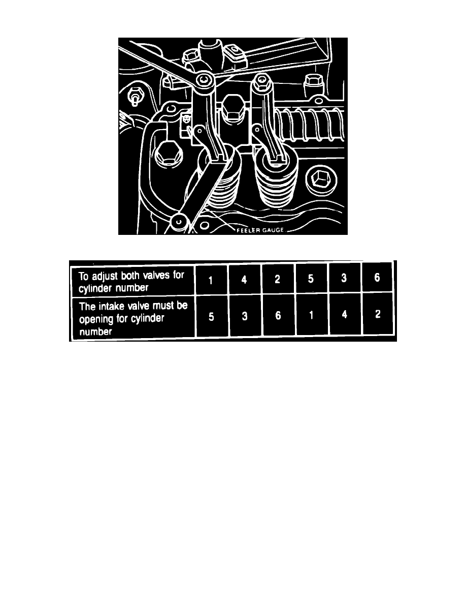
Fig. 1 Adjusting valve clearance. V6-171
Fig. 2 Valve clearance adjustment chart. V6-171
CValves, Adjust
V6-171 ENGINE
When checking valve clearance, insert feeler gauge between valve tip and rocker arm at front or rear of valve tip and move gauge in a
forward or rearward motion parallel to the crankshaft center line. If feeler gauge is inserted at outboard edge and moved perpendicular to
crankshaft center line, a false indication will be given, resulting in tight valve clearance.
1.
Remove rocker arm cover.
2.
Rotate engine slightly until cylinder No. 5 intake valve just begins to open. This can be verified by placing a finger on intake valve rocker arm
adjusting screw for cylinder No. 5 and feeling for movement while turning engine.
3.
Adjust intake and exhaust valves on No. 1 cylinder to .014C inch for intake valves and .016C inch for exhaust valves, by tightening or loosening
adjusting screw as necessary, Fig. 1.
4.
Adjust remaining valves in firing order by positioning cam according to chart, Fig. 2.
Valve Arrangement
Front to Rear
V6-171 Right Bank.................................................................................................................................................................................................I-E-I-E-E-I
V6-171 Left Bank....................................................................................................................................................................................................I-E-E-I-E-I
V6-177 Right Bank.................................................................................................................................................................................................E-I-E-I-E-I
V6-177 Left Bank....................................................................................................................................................................................................I-E-I-E-I-E
V6-183, 232 Left Bank............................................................................................................................................................................................I-E-I-E-I-E
V6-183, 232 Right Bank.........................................................................................................................................................................................E-I-E-I-E-I
V6-232 Right...........................................................................................................................................................................................................I-E-I-E-I-E
V6-232 Left.............................................................................................................................................................................................................E-I-E-I-E-I