
Ranger 4WD V6-171 2.8L (1983)
Wheel Bearing: Adjustments
With Automatic Locking Hubs
THIS ARTICLE INCLUDES CHANGES MADE BY TSB #85-5-27 DATED MARCH 1985
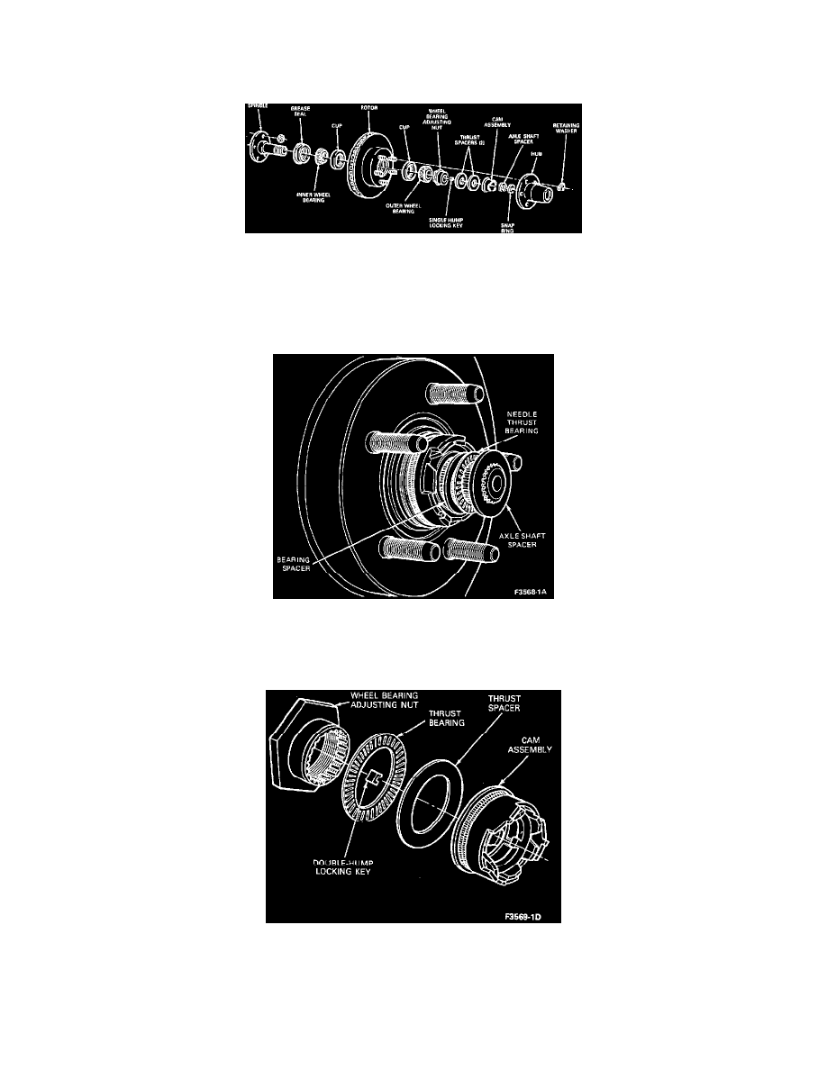
Fig. 6 Automatic Locking Hub
1. Raise the vehicle and install safety stands.
2. Remove the wheel and tire assembly.
3. Remove the retainer washers from the lug nut studs and remove the automatic locking hub assembly from the spindle.
4. Remove the snap ring from the end of the spindle shaft.
Axle Shaft Spacer, Thrust Bearing And Bearing Spacer
5. Remove the axle shaft spacer, needle thrust bearing and the bearing spacer.
Wheel Bearing Adjusting Nut Assembly
6. Being careful not to damage the plastic moving cam, pull the cam assembly off the wheel bearing adjusting nut and remove the thrust washer and
needle thrust bearing from the adjusting nut.
CAUTION: To prevent damage to the spindle threads, remove adjusting nut locking key from spindle keyway located under adjusting nut prior