
Ranger 4WD V6-182 3.0L (1994)
Axle Shaft: Service and Repair
Axle Shaft, Conventional Fixed/Floating
All Except 3.73:1 and 4.10:1
REMOVAL AND INSTALLATION
1. Raise and support vehicle.
2. Remove rear wheels and brake drums.
3. Drain rear axle lubricant by removing housing cover.
4. Remove axle shafts as follows:
a. Remove differential pinion shaft lock bolt and the shaft.
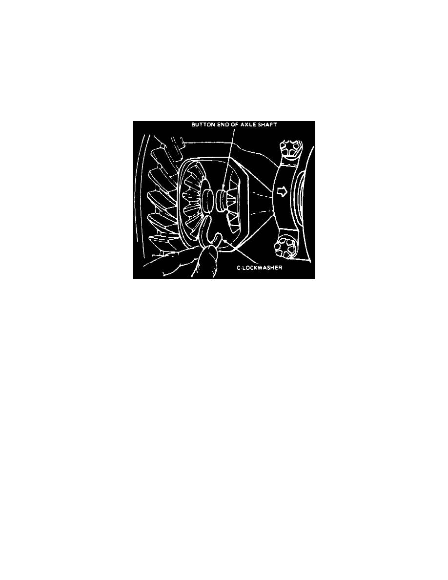
Fig. 4 Axle Shaft Removal
b. Push axle shafts inward toward center of vehicle and remove C-lockwashers from shafts, Fig. 4.
c. Carefully slide axle shafts out of housing.
5. Remove seal and bearing using a suitable hook-type puller.
6. Reverse procedure to install, noting the following:
a. Apply suitable grease between lips of axle shaft seal.
b. Install bearing using axle tube bearing replacer tool No. T78P-1225-A, and install seal and using axle tube seal replacer tool No. T78P-1177-A
or equivalents.
c. Tighten differential pinion shaft lock bolt to 15-30 ft lb Housing cover bolts to 25-35 ft lb Housing cover ratio tag bolt to 15-24 ft lb.
NOTE: Whenever a plastic axle housing cover is removed, it must be replaced with a new cover and bolts. On plastic axle housing covers
torque bolts to 15-20 ft lb.
d. Add rear axle lubricant EOAZ-19580-AA or equivalent until it is 6-14 mm (1/4 - 9/16 inch) below the fill hole. Add 4oz. of friction modifier
C8AZ-19B546-A or equivalent for Traction-Lock(r) rear axle assemblies.
Right Hand Slip Yoke and Stub Shaft Assembly (4WD)
REMOVAL AND INSTALLATION
1. Disconnect sensor two-pin connector from wiring harness inside engine compartment.
2. Separate sensor cable from brake hose clips, then remove retaining bolt of front anti-lock sensor from front wheel spindle and slide front anti-lock
sensor out of mounting hole.
3. Raise and support vehicle. Install jack stands under radius arm brackets.
4. Disconnect driveshaft from front axle yoke, then remove front wheels.
5. Remove disc brake calipers and position aside.
NOTE: Do not let caliper hang down on brake hose.
6. Remove stabilizer bar and links.
7. Disconnect steering linkage from spindle by removing the cotter pin and retaining nut.
8. Place a jack under axle arm assembly and compress the coil spring, then remove nut which retains bottom of spring to axle arm.
9. Lower axle until all spring tension is released, then remove the coil spring, spacer, seat and stud.