
Ranger 4WD V6-182 3.0L (1994)
Reverse Gear Shaft: Service and Repair
REMOVAL
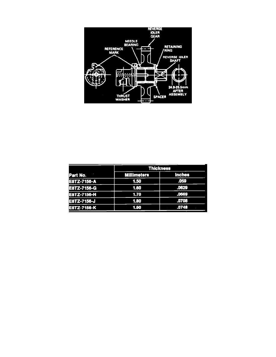
Cross-Sectional View Of Reverse Idler Gear Shaft
1. Remove retaining ring, spacer, idle gear, needle bearings, and thrust washer from reverse idler gear shaft.
INSTALLATION
1. Install thrust washer onto reverse idler gear shaft. Ensure tab on thrust washer mates with groove on reverse idler shaft to prevent rotation of thrust
washer.
2. Install needle bearings, idler gear, and spacer.
3. Install original retaining ring onto reverse idler gear shaft, then insert a suitable feeler gauge between retaining ring and reverse idler gear to
measure end play.
Reverse Idler Gear Selective Retaining Ring Chart
4. Endplay should be 0.1-0.2 mm (0.0039-0.0078 in). If endplay is not as specified, select a suitable retaining ring from the Reverse Idler Gear
Selective Retaining Ring Chart that will bring endplay to within specifications.