
Ranger 4WD V6-183 3.0L (1993)
Brake Rotor/Disc: Service and Repair
Refinishing
Servicing of disc brakes is extremely critical due to close tolerances required in machining the brake disc to insure proper brake operation.
Maintenance of these close controls on friction surfaces is necessary to prevent brake roughness. In addition, surface finish must be non-directional
and maintained at a micro-inch finish. This close control of the rubbing surface finish is necessary to avoid pulls and erratic performance and promote
long lining life and equal lining wear of both left and right brakes.
In light of the foregoing remarks, refinishing of the rubbing surfaces should not be attempted unless precision equipment, capable of measuring in
micro-inches (millionths of an inch) is available.
To check runout of a disc, mount a dial indicator on a convenient part (steering knuckle, tie rod, disc brake caliper housing) so that the plunger of the
dial indicator contacts the disc at a point one inch from the outer edge. If the total indicated runout exceeds specifications, install a new disc.
To correct a shudder/vibration/pulsation condition possibly related to the brake rotor, first check the wheel bearing adjustment and correct as
necessary. Remove any build-up of foreign material on linings or rotor surfaces by hand sanding friction surfaces.
Lathe turn the rotor if hand sanding of any foreign matter on friction surfaces does not correct the condition, or if measured runout exceeds 0.010 inch
total indicator reading.
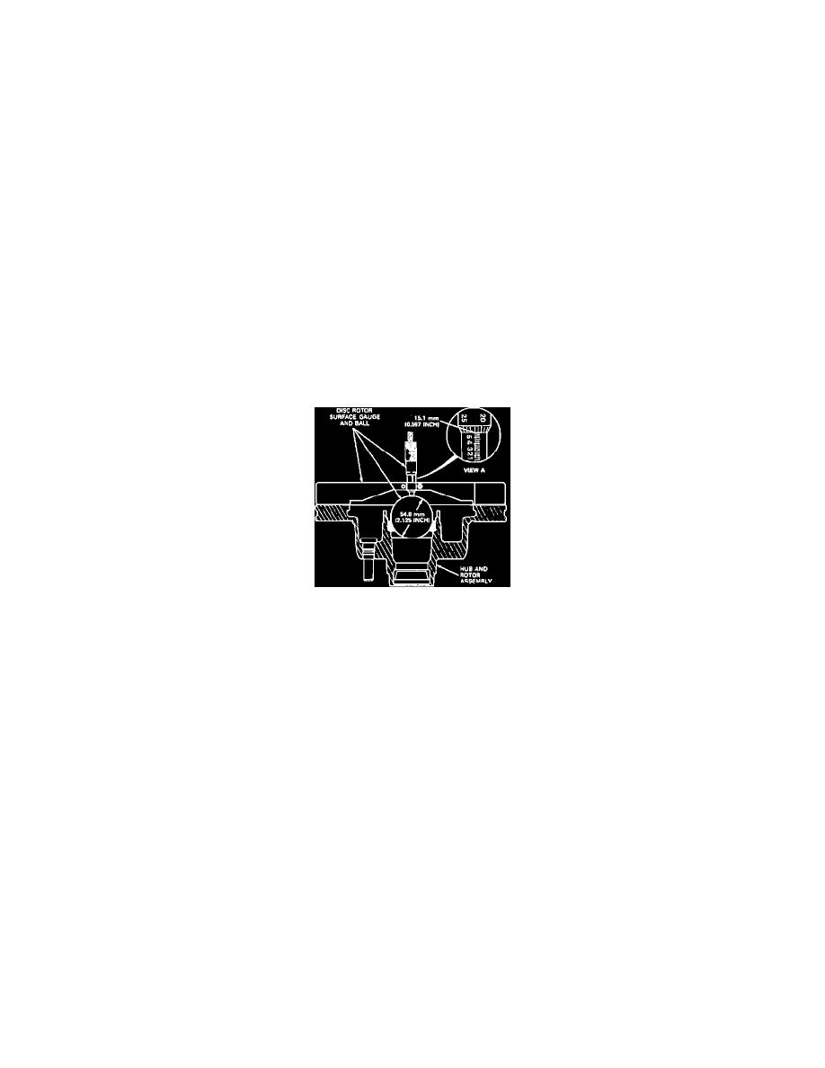
Maximum allowable stock removal of the inner rotor braking surface is determined by the use of Disc Rotor Gauge and Ball tool No. T71P-1102-A or
equivalent. Rotor minimum thickness must not be less than shown in specifications nor less than the number cast on the inside of the rotor
after refinishing.
Fig. 1 Guaging Front Rotor Inner Braking Surface
Measure rotor thickness as follows:
1. Remove the inner grease retainer and bearing assembly from the hub and rotor assembly.
2. Carefully place the gauge ball in the bearing cup as shown in Fig. 1, (do not drop ball into place).
3. Set the micrometer to the base line setting dimension of 0.256 inch.
4. Position the micrometer gauge bar on the rotor inner braking surface with the micrometer centered over the ball. If the micrometer end touches
the ball or has to be retracted in order to correctly sit on the rotor, no additional stock removal is allowed and the rotor must be replaced.
5. Calculate the difference between reading and the base line setting. This distance is equal to the maximum allowable stock removal from the inside
braking surface only.
6. Check the rotor for the maximum amount of stock that can be removed from the rotor thickness. Measure actual rotor thickness with micrometer
and subtract minimum allowable thickness (cast in individual rotor). Total material removal (combination of both sides) must not exceed this
amount. If the rotor thickness is less than the minimum, the rotor must be replaced, regardless of the gauge bar and ball measurement.
Rotor minimum thickness is also shown on each rotor.
7. Set the cutting tool to just contact the high spots on the rotor, then adjust the cutting tool to the minimum depth required to clean up the rotor
surface. Never use a lathe that cuts only one face of the rotor at a time, it must be a simultaneous straddle cut.