
Ranger 4WD V6-183 3.0L (1993)
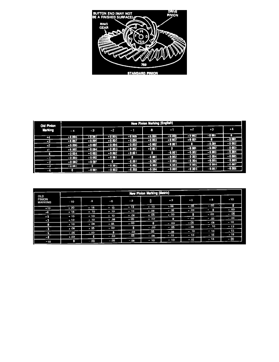
Fig. 6 Ring And Pinion Identification
On the button of each drive pinion is marked a plus (+), a minus (-) or a zero (0), Fig. 6. These markings indicate the position for each gear set. The
position is determined by thickness of baffle between inner pinion bearing cup and carrier bearing bore and thickness of selective oil slinger between
pinion head and and inner pinion bearing. Any pinion depth change is made by changing thickness of selective oil slinger.
If the original gear set is being re-used, measure original baffle and selective slinger and replace with exact same size, if necessary.
Fig. 7 Drive Pinion Adjusting Shim Thickness Chart
Fig. 8 Drive Pinion Adjusting Shim Thickness Chart (Metric)
If a new gear set is being used, notice the plus (+), minus (-) or zero (0) etchings on both original and new drive pinion and adjust thickness of new
selective oil oil slinger according to charts in Figs. 7 and 8.