
Ranger 4WD V6-245 4.0L VIN X SFI (1999)
Camshaft Position Sensor: Service and Repair
Synchronizer
Removal And Installation Synchronizer-Camshaft
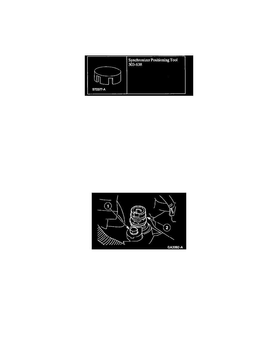
Special Tool
Removal
CAUTION: The No. 1 cylinder must be set on top dead center (TDC) of the compression stroke or the synchronizer assembly will not be installed
correctly.
CAUTION: Do not turn the crankshaft or the camshaft during the removal and installation procedure or the fuel system timing will be out of time
with the engine and possibly cause engine damage.
1. Rotate the crankshaft until the No.1 cylinder is at TDC of the compression stroke and the TDC mark lines up with the timing mark.
Note: Prior to the removal of the camshaft position (CMP) sensor, note the position of the CMP sensor electrical connector. The installation
procedure requires that the electrical connector be located in the same position.
2. Remove the CMP sensor. For additional information, refer to Camshaft Position (CMP) Sensor in this section. See: Camshaft Position (CMP)
Sensor
Note: The oil pump driveshaft might not come out with the camshaft synchronizer. If so, retrieve the oil pump drive shaft before proceeding.
3. Remove the camshaft synchronizer.
1. Remove the bolt.
2. Remove the synchronizer.
Installation
CAUTION: After installation, do not loosen the synchronizer bolt and rotate the synchronizer assembly. The synchronizer assembly is not adjustable.
Do not loosen the synchronizer bolt after the alignment tool has been removed in order to align the CMP electrical connector for any reason. If the
electrical connector is not in the correct position, the synchronizer assembly must be removed, the alignment tool and the assembly reinstalled if the
engine has not been rotated from top dead center (TDC) of the compression stroke on the No. 1 cylinder.