
Ranger 4WD V6-3.0L (2008)
5. Close the glove compartment door.
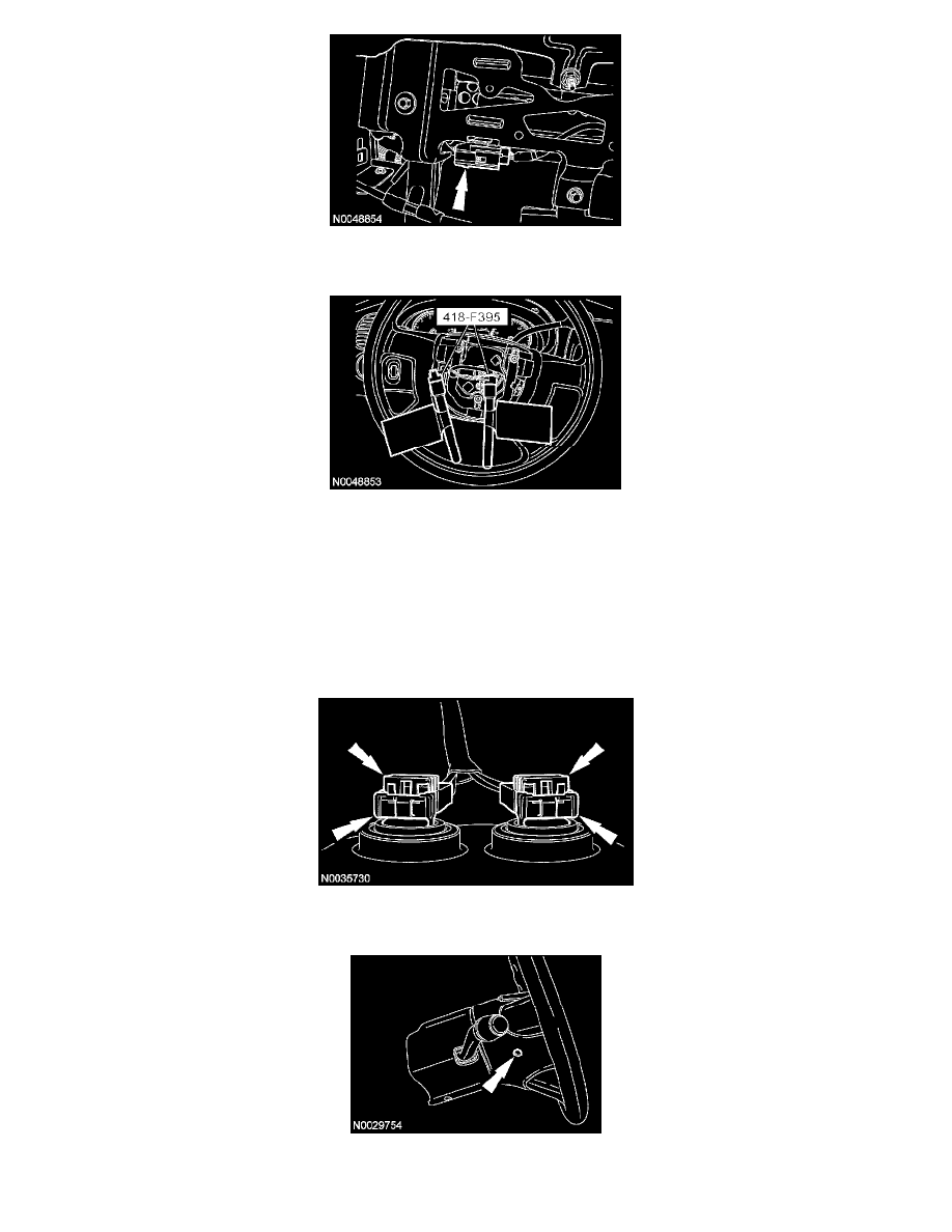
6. Remove the restraint system diagnostic tools from the clockspring electrical connectors at the top of the steering column.
7. CAUTION:
-
Do not install the driver air bag module electrical connectors by the locking buttons. Damage to the locking buttons may occur.
-
The driver air bag module electrical connector locking buttons must be in the released position when the connector is being installed
or connector damage may occur.
-
The driver air bag module electrical connectors are unique and cannot be reversed when connected to the driver air bag module.
Match the electrical connector key to the keyway in the driver air bag module. Do not force the electrical connectors into the driver
air bag module. Damage to the connector or component may occur.
With the locking buttons released, install the driver air bag module electrical connectors fully into the driver air bag module and seat the locking
buttons.
8. Install the 2 driver air bag module bolts (1 shown).
-
Tighten to 6 Nm (53 lb-in).
9. WARNING: Remove restraint system diagnostic tools from the vehicle prior to road testing. If tools are not removed, the supplemental
restraint system (SRS) device may not deploy in a crash. Failure to follow this instruction may result in serious personal injury or death