
Ranger 4WD V6-3.0L (2008)
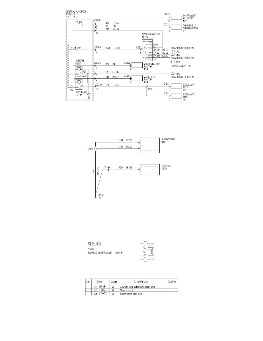
Power and Ground Distribution Diagrams shows the current feed circuits. The current path is shown from the battery to the ignition switch and to all
fuses. It also shows the circuits protected by each fuse. The circuit is traced from the fuse to the component. All details (wires, splices, connectors)
between the fuse and the first component are shown.
Ground Distribution
Power and Ground Distribution Diagrams contains the diagram that shows the complete details for each ground connection or main ground splice.
This is useful in diagnosing a problem affecting several components at once (poor ground connection or ground splice). All details (wires, splices,
connectors) between the ground point and the component are shown. These ground connection details are shown here in order to keep the individual
set diagrams as uncluttered as possible.
Component and Connector Information
C904
Connector Views show the views of the pins and/or cavities of all connectors. The pin and cavity sides are shown separately as if the connector were
disconnected. The color of the connector housing is indicated next to the connector number when available. The harness causal number is located
above the connector view and below the connector number. The circuit function charts are located below each connector. The wiring harness
designations are listed in Component Location Charts.