
Ranger 4WD V6-3.0L (2008)
1
= Proper crimp
2
= Insulation not removed
3
= Wire strands missing
4
= Intermittent signals through pierced insulation
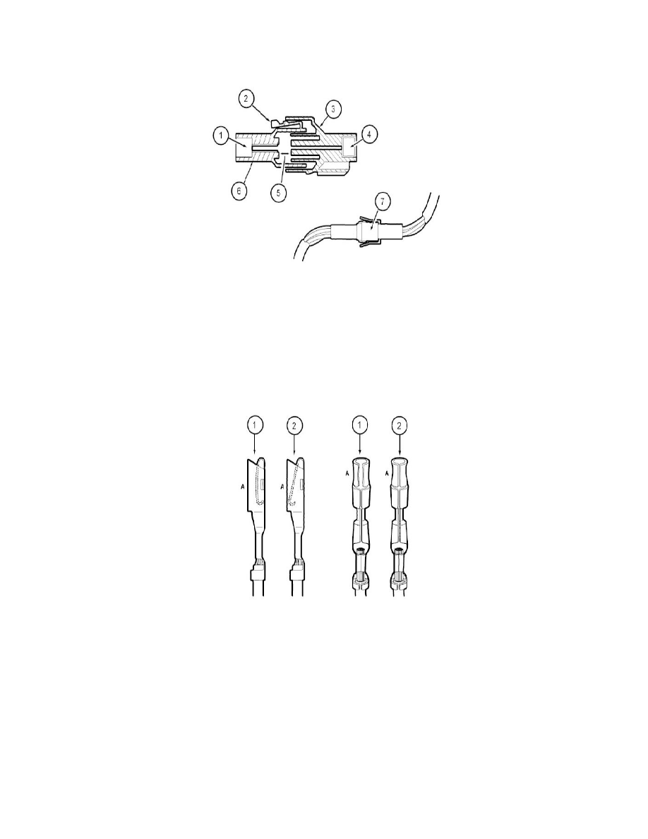
Partially mated connectors
1
= Seal
2
= Displaced tab
3
= Female half
4
= Seal
5
= Intermittent contact
6
= Male half
7
= Intermittent contact
Lock may be displaced into an unlocked position; pull on the connector to verify the lock.
Deformed (enlarged) female terminals
1
= Enlarged
2
= Normal
Any probe entering the terminal may enlarge the contact spring opening creating an intermittent signal.
Insert the correct mating terminal (Location A) from the service kit and feel for a loose fit.