
Ranger 4WD V6-3.0L VIN U (1997)
2. Position new front brake anti-lock sensor indicator on hub. Using a cylinder with 79 mm (3.1-in.) ID and 96 mm (3.8-in.) OD, press the front
brake anti-lock sensor indicator onto the hub. The front brake anti-lock sensor indicator must be fully seated against the shoulder in the hub.
CAUTION: When performing the following step' make sure indicator ring is pressed on straight.
3. Install hub, rotor and caliper assemblies.
4. Install wheel and tire assembly. Tighten wheel lugnuts to 135 Nm (100 ft. lbs.).
Rear
NOTE: To service the speed sensor ring, the differential case must be removed from the axle housing.
REMOVAL
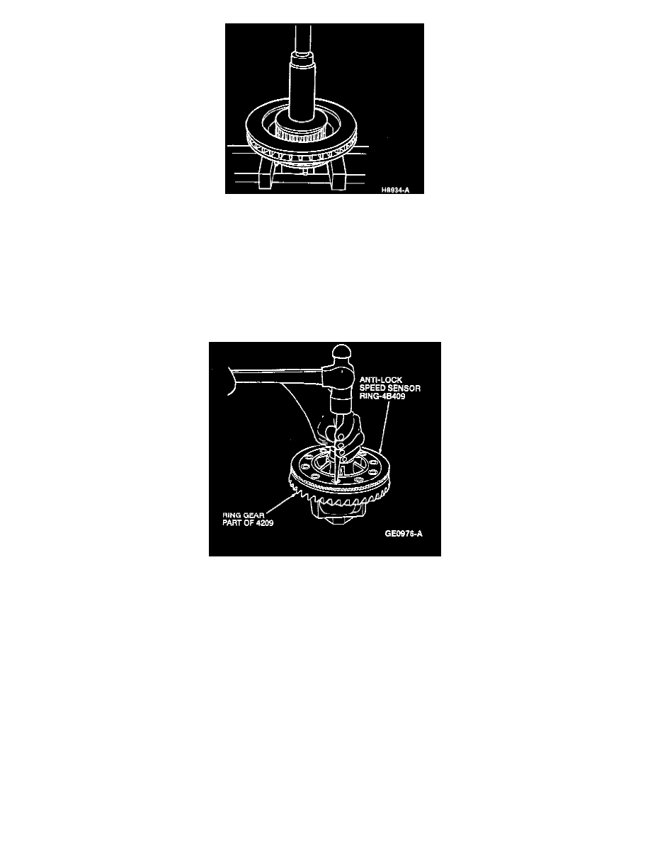
1. Remove the bolts retaining the ring gear to the differential case. Remove the ring gear by striking at alternate holes around the gear.
CAUTION: Extreme care should be taken not to scratch, dent, chip or otherwise cause damage to anti-lock brake sensor ring teeth while handling
or during assembly.
NOTE:
^
Before removing ring gear inspect it and determine if ring runout check is necessary.
^
Do not remove anti-lock speed sensor ring unless replacement is required. It does not have to be removed for ring gear replacement.