
Ranger 4WD V6-3.0L VIN U (1997)
Evaporator Case: Service and Repair
REMOVAL
1. Disconnect the ground cable.
2. Recover the refrigerant system. Observe all safety precautions. See: Service and Repair
3. Disconnect the electrical hardshell connectors from the blower motor, the heater blower motor switch resistor, and the A/C cycling switch.
4. Disconnect the vacuum line (part of A/C blower motor feed extension) from the A/C vacuum check valve.
5. Disconnect the vacuum line (part of the vacuum assembly) from the vacuum source on the engine intake manifold; then, remove the line from the
routing channel.
6. Disconnect the condenser to evaporator tube from the inlet tube and cap the openings to prevent the entry of dirt and moisture.
7. Disconnect the A/C manifold and tube from the suction accumulator/drier.
8. Remove speed control module from fender.
9. Remove the coolant recovery reservoir.
10. Remove the solenoid box cover, if so equipped, by removing the three bolts fastened through the fender liner. Remove the air cleaner and A/C
vacuum reservoir tank and bracket, if so equipped.
11. Remove three nuts from the engine compartment side of the A/C evaporator housing and one nut from the passenger compartment side of the A/C
evaporator housing.
12. Remove the A/C evaporator housing from the vehicle.
INSTALLATION
1. Position the A/C evaporator housing to the dash panel and install the three retaining nuts in the A/C evaporator housing and one nut in the
passenger compartment.
2. Install the air cleaner, speed control module, and coolant recovery reservoir.
3. Using a new O-ring lubricated with clean refrigerant oil, connect the condenser to evaporator tube to the inlet tube.
4. Connect the A/C manifold and tube to the suction accumulator/drier outlet tube after checking for a missing or damaged garter spring and/or
repairing or replacing the spring. Install two new specified (special material) O-rings, lubricated with clean refrigerant oil onto the coupling male
fitting.
5. Connect the vacuum line to the A/C vacuum check valve.
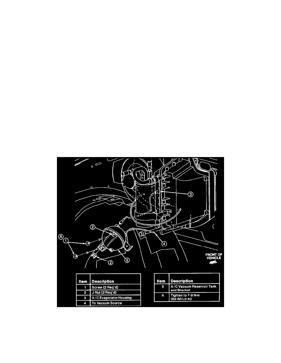
Vacuum Reservoir Installation
6. Connect the vacuum line (part of A/C vacuum reservoir tank and bracket) to the source on the engine intake manifold and route it as shown in the
Vacuum Reservoir Installation image.
7. Connect the electrical hardshell connectors to the heater blower motor switch, the A/C cycling switch, and the blower motor.
8. Leak test, evacuate and charge the system. Observe all safety precautions. See: Service and Repair
9. Connect battery ground cable.