
Ranger 4WD V6-3.0L VIN U (1997)
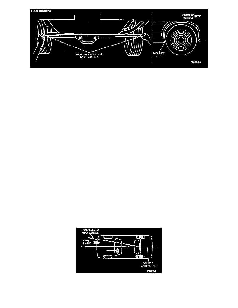
5. Rotate the rear wheels so the markings face the rear of the vehicle. Again, measure and record the distance between scribe marks (rear reading).
6. The difference between the front and rear readings is the toe-out or toe-in condition of the axle housing (Steps 3 and 5).
All numbers are for example only.
Front reading: 52-3/16 inch
Rear reading: 52-1/16 inch
Toe-out: 2/16 inch or 1/8 inch Toe-in occurs when the front reading is less than the rear reading.
7. To determine camber, find the average of the front and rear readings (obtained in Steps 3 and 5). Then, subtract the bottom reading from this
(obtained in Step 4).
Average of front and rear readings: 52-2/16 inch
Bottom reading: 52-2/16 inch
Difference or camber: 0 inch Positive (+) camber is when the bottom reading is less than the average of the front and rear readings. Negative
(-) camber is when the bottom reading is greater than the average of the front and rear readings.
8. Results of the measurements taken must conform to the following specifications:
Tape measure specification:
Camber: ± 5/32 inch
Toe-in: 0-1/16 inch
Toe-out: 0-3/16 inch
If the axle housing does not meet this specification, it must be replaced.
9. If the axle housing is replaced, repeat Steps 2 through 7.
Rear Axle Adjustments (Dogtracking)
1. Verify that the vehicle dogtracks by performing the diagnostic procedure.
NOTE: A warped or bent rear axle assembly or bent frame can cause a vehicle to "dogtrack" and should be considered during diagnosis.
2. Raise the vehicle off the ground using a frame-mounted hoist or equivalent. Do not hoist the vehicle using the rear axle assembly as a lift point.
3. Remove the U-bolts which attach the rear axle assembly to the rear leaf springs on the side of the rear axle assembly which will be moved. Allow
the axle to drop down. The shock absorber will support the axle assembly.
4. Using C-clamps, clamp the leafs of the leaf spring together on both sides of the center bolt and remove the bolt.
5. If thrust angle is 0 to 0.3 degrees modify the spring center bolt on the side of the axle which must be moved.