
Ranger 4WD V6-3.0L VIN U (1997)
Step 1 - Tone and Door Ajar Lamp Test
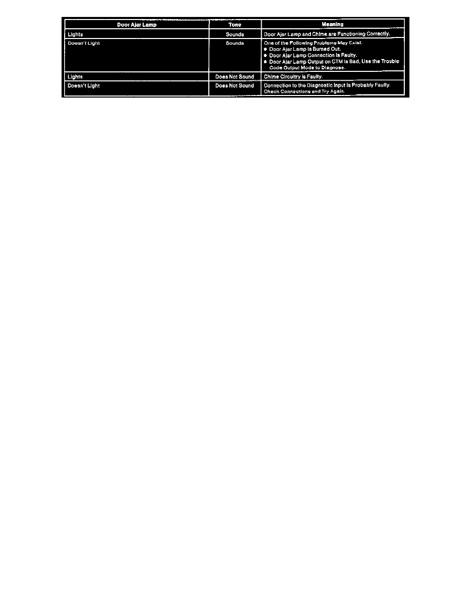
When the diagnostic mode is first entered, the CTM will generate a tone and light the door ajar lamp for three seconds. If the key is in the RUN or
ACCY position, use the following table to diagnose problems entering the diagnostic mode.
After the three-second test, the CTM will pause for one-second and then proceed to either Step 2 or Step 3 depending on whether the key is in the
ignition.
The diagnostic mode is used to test the central timer module (CTM) and associated connections while the CTM is in the vehicle. While in this mode,
the technician can retrieve and clear the internally stored trouble codes and also individually test each of the OTM inputs. The normal CTM functions
are disabled while in the diagnostic mode. The wiper functions are also disabled while in the diagnostic mode. The wiper motor output is operated by
the washer switch input during the input test to allow testing of the wiper motor status switch input.
Step 2 - Trouble Code Output
When the OTM is in the normal mode of operation, it is continually monitoring itself. When a fault occurs it is recorded. The trouble code output
mode shows these codes, if any, to the technician by flashing the door ajar lamp and simultaneously sounding the chime in a certain order. These
codes may then be used to help diagnose potential intermittent failures.
Step 3 - Input Test
The input test allows an operator to individually test the CTM inputs. It is entered when the operator puts the key in the ignition. The inputs may be
cycled in any order. As an input is toggled on or off, the door ajar lamp and tone outputs will be activated for one second for confirmation. At any
time, if the key is removed from the ignition assembly, the trouble code output will be re-entered.
Viewing Trouble Codes
Trouble codes are output to the operator through flashing of the door ajar lamp and sounding of the chime. Each code is represented by a two-digit
number. The high digit is output first followed by a one second pause followed by the second digit. Each two-digit code is separated by a three-second
pause. Each digit is also made up of one to nine one-second lamp flashes.
Trouble Code Chart
Code .................................................................................................................................................................................................................. Description
11 ............................................................................................................................................................................... No trouble codes are currently stored.
12 ........................................................................................................................................... The wiper/washer mode switch was open at least 30 seconds.
13 .......................................................................................................................................... The wiper delay interval switch was open at least 30 seconds.
14 ......................................................................................................................................................................... An internal software failure was detected.
15 ........................................................................................................................................................................ An internal hardware failure was detected.
21 ..................................................................................................................................................................... The wiper/high low speed relay coil shorted.
22 .............................................................................................................................................................................. The wiper/brake run relay coil shorted.
23 .................................................................................................................................................................................. The battery saver relay coil shorted.
24 .................................................................................................................................................................................................. The courtesy coil shorted.
31 .................................................................................................................................................................................. The washer pump relay coil shorted.
32 .............................................................................................................................................................................. The safety belt lamp relay coil shorted.
34 ........................................................................................................................................................................................ The door ajar relay coil shorted.
NOTE: The entire set of stored trouble codes will be repeated indefinitely until either the input test mode is entered or the ground is removed from the
diagnostic input. This table shows all of the possible trouble codes.
Inspection and Verification
Inspection and Verification
The Generic Electronic Module (GEM) diagnostic system is composed of the New Generation STAR (NGS) tester, the GEM and all GEM-associated
components. They allow you to determine if a GEM subsystem has a fault and provides the capability to isolate the fault.
NOTE: This diagnostic information contains only on-demand self-test and functional test procedures for the GEM and GEM-related subsystems and
power and ground concern isolation pinpoint tests. Refer to the testing for the affected system for GEM subsystem diagnostic procedures.