
Ranger 4WD V6-3.0L VIN U (1997)
Drive/Propeller Shaft: Service and Repair
Rear
Balancing
DESCRIPTION
Vibration or shudder which is noticeable either on fast acceleration, when coasting, or when using the engine for braking, may be caused by the rear
axle housing being loose on the rear suspension improper tire balance, improper driveline installation, or driveline balance.
If driveshaft components are replaced and shaft vibration is encountered after installation disconnect the driveshaft and remove the driveshaft. Rotate
the rear axle companion flange 180 degrees; then, reconnect the driveshaft to the driveshaft slip yoke and reinstall in vehicle. If the vibration persists,
disconnect the driveshaft at the rear axle companion flange. Rotate the rear axle companion flange 180 degrees and reconnect the driveshaft to the rear
axle companion flange.
If rotating the driveshaft 180 degrees does not eliminate vibration, the driveshaft may be balanced, using the following procedure:
DRIVESHAFT BALANCING
1. Raise the vehicle on a twin-post hoist so that both the front and rear axles are safely supported with all wheels free to rotate.
2. Remove the rear wheels and tires. Reinstall lugnuts to retain brake drums or rotors.
3. With the transmission in gear, increase the vehicle speed to the maximum vibration level. Note and record the speed of this vibration period as a
baseline speed.
4. With the transmission in gear, run the vehicle with the driveshaft rotating at a speedometer speed of 64-80 km/h (40-50 mph), have an assistant
carefully bring a crayon, piece of chalk, or colored pencil up until it just barely contacts the rear end, center and front end of the driveshaft. The
chalk marks will indicate the heavy side of the driveshaft. Use caution when checking the driveshaft near the balance weights to prevent injury to
the hands.
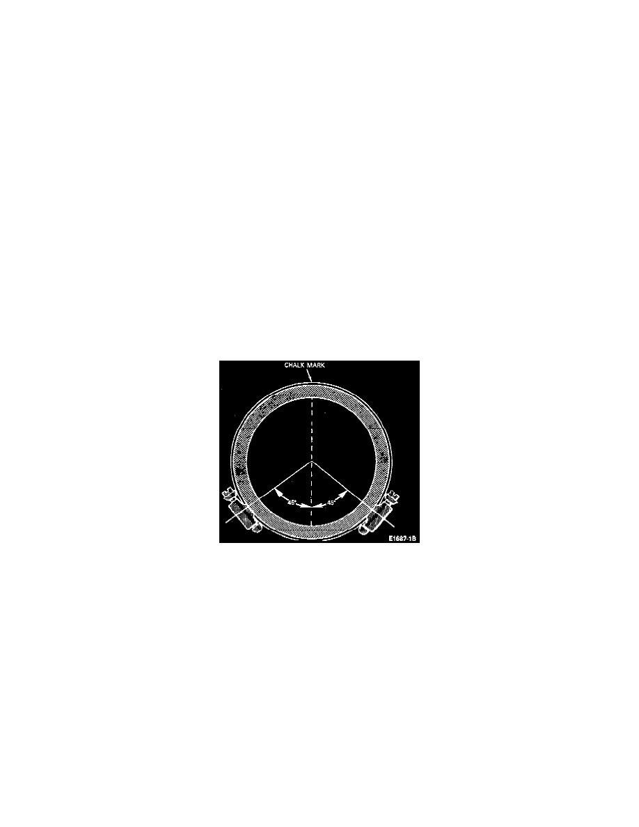
5. Install two screw-type hose clamps on the driveshaft so that their heads are located 180 degrees from the chalk mark, starting at the pinion yoke
end of the driveshaft. Tighten the clamps.
6. Run the vehicle up to the baseline speed. If vibration is still evidenced, rotate the clamps approximately 45 degrees away from each other and test
for correction of vibration.
CAUTION: To prevent overheating, do not run the vehicle on the hoist for an extended period.
7. If necessary, continue to rotate the clamps apart in smaller increments until the vibration is eliminated or begins to be reduced.
8. If the vibration is not completely eliminated, repeat the foregoing procedure and balance the front end of the driveshaft, checking for elimination
or reduction in the vibration level.
9. Reinstall wheels and tires.
10. Remove the vehicle from the hoist and road test.
ALTERNATE PROCEDURE
1. Road Test-Evaluate and record road speed at which vibration occurs.
2. Raise vehicle on a frame contact hoist. Remove the wheels and tires. Reinstall lugnuts to retain drums or rotors. Re-evaluate by starting the engine,
engaging the transmission and accelerating to the indicated speeds at which the vibration was most severe during the road test. Suspending the rear
axle assembly makes the driveline more sensitive to vibration.