
Ranger 4WD V6-3.0L VIN U (1997)
Drive/Propeller Shaft: Testing and Inspection
Driveshaft Runout and Balance
Driveline vibration exhibits a higher frequency and lower amplitude than does high-speed shake. Driveline vibration is directly related to the speed of the
vehicle and is usually noticed at speeds of 72 km/h (45 mph) or higher. Driveline vibration can be perceived as a tremor in the floor pan or is heard as a
rumble, hum or boom. Driveline vibration can exist in all drive modes, but may exhibit different symptoms depending upon whether the vehicle is
accelerating, decelerating, floating or coasting. If the vibration is particularly noticeable during acceleration or deceleration, especially at lower speeds,
then driveline angle should be checked. Driveline vibration can be duplicated by supporting the axle upon a hoist or upon jackstands, though the brakes
may need to be applied lightly in order to simulate road resistance.
1. Raise vehicle promptly after road-testing, on twin-post hoist or jackstands, to prevent tire flat-spotting. Engage drivetrain and run-up to observed
road test speed to verify presence of vibration. If not evident, check non-driving wheels with wheel-balancer spinner to rule out imbalance as a
possible cause. Unlock front hubs or remove hub covers before spinning wheels. If required, balance non-driving wheels and repeat road test. If
vibration is still evident, proceed to Step 3.
2. If vibration appeared in road-speed hoist test, mark relative position of drive wheels on rear axle assembly or hub lugs to permit reinstallation in
original position, and remove wheels. Secure brake drums, if present, by installing all lugnuts in reversed position and repeat road-speed run-up. If
vibration is gone, check drive wheel runout and balance. If vibration persists, proceed to Step 3.
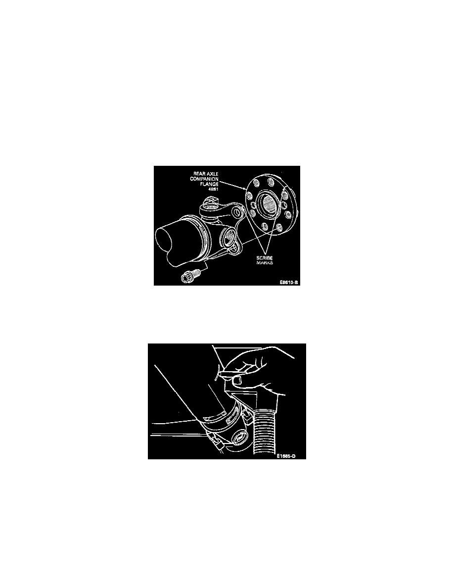
3. Inspect driveshaft for signs of physical damage, missing balance weight, undercoating, or improperly seated, worn, or binding universal joints.
Check the index marks (paint spots) on rear of driveshaft and rear axle companion flange. If these marks are more than 45 degrees apart,
disconnect driveshaft and reindex to align marks as close as possible. Clean driveshaft and replace universal joints as necessary, or replace
driveshaft if damaged. After any corrections are made, recheck vibration at road test speed. If gone, reinstall wheels and road test. If vibration
persists, proceed to Step 4.
4. With vehicle on hoist and wheels off, measure runout at front, center, and rear of driveshaft with indicator, rotating driveshaft by turning a brake
drum or rotor. On a one-piece driveshaft, if runout exceeds 0.89 mm (0.035 inch) at front or center, the driveshaft must be replaced. If front and
center are within this limit, but rear runout is not, mark the rear runout high point and proceed to Step 5. If runout is within limits at all points,
proceed to Step 7 or Adjustments, Driveshaft Balancing.
5. Circular rear axle companion flanges can be indexed in 45-degree increments to fine tune the runout condition. Check runout at rear of driveshaft,
and if still over 0.89 mm (0.035 inch), mark high point and see Step 6. If runout is no longer excessive, check for vibration at road test speed, and,
if still present, reindex the driveshaft slip yoke on the transmission output shaft 180 degrees and road test the vehicle. If the vibration persists,
proceed to Step 7 or Adjustments, Driveshaft Balancing.
NOTE: Move universal joints in each direction of rotation during reindexing. If a universal joint feels stiff or has a gritty feel in any direction,
replace the rear axle universal joint.