
Ranger 4WD V6-3.0L VIN U (1997)
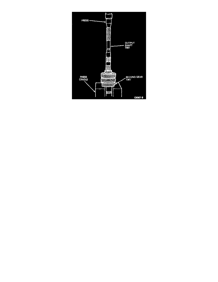
4. Position mainshaft, with rear end (long side of flange) facing upwards into press using Pinion Bearing Cone Replacer T53T-4621-B as a press
plate, and Bearing Cone Replacer T88T-7025-B to protect inner race rollers.
CAUTION: Make sure that flange does not contact or ride up onto press cradle. Improper positioning can result in component damage.
5. Press off the following components as a unit:
^
Bearing
^
Input bearing spacer
^
First gear (1GR)
^
First and second speed gear bearing
^
First/second synchronizer
^
First/second Synchronizer blocking rings
^
Second gear (2GR)
^
First and second speed gear bearing.
ASSEMBLY
NOTE:
^
Make note of the differences between the third gear synchronizer blocking ring and the first, second and fourth gear synchronizer blocking
rings. The third gear synchronizer blocking ring has three teeth cut out 120 degrees apart from each other. Directly adjacent to one side of the
missing teeth, two teeth have been bridged together. This is to help eliminate any upshift "crunch" that may occur.
^
To install components onto output shaft, position components as illustrated. Press components into position using Pinion Bearing Cone
Replacer T53T-4621-B and Axle Bearing/Seal Plate T75L-1165-B.
^
Make sure that bearing is still positioned in case.