
Ranger 4WD V6-3.0L VIN U (1997)
Seals and Gaskets: Service and Repair
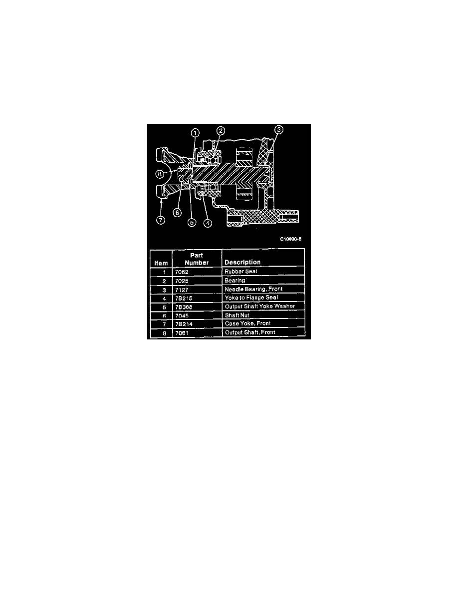
Borg-Warner 13-54 Manual Shift
Front Output Shaft
REMOVAL
1. Place transfer case in 4WD, set automatic transmission in Park, manual transmission in gear.
2. Raise the vehicle on a hoist and position suitable safety stands under vehicle.
3. If equipped, remove the damper from the transfer case and the skid plate from the frame.
4. Place a drain pan under the transfer case, remove the drain plug and drain the fluid from the transfer case.
5. Remove the driveshaft from the front output shaft and wire the driveshaft out of the way.
6. Using a 30 mm thin-wall socket, remove the front output shaft nut, output shaft yoke washer, rubber seal and front case yoke.
7. Remove the yoke to flange seal from the front output housing bore by prying and pulling on the curved-up lip of the yoke to flange seal or use the
Impact Slide Hammer T50T-100-A to pop off the yoke to flange seal. Do not damage the bearing, bearing cage or case.
INSTALLATION
1. Make sure the housing face is free from nicks and burrs. Coat the yoke to flange seal with Premium Long-Life Grease XG-1-C or -K or equivalent
meeting Ford specification ESA-M1C75-B. Position the seal into the front output housing bore, making sure the seal is not cocked in the bore.
Drive the seal into the bore with Output Shaft Seal Replacer T83T-7065-B and Driver Handle T80T-4000-W.
2. Install the front case yoke, rubber seal, output shaft yoke washer and the nut. Tighten the nut to 203-244 Nm (150-180 ft. lbs.).
3. Connect the front driveshaft to the front case yoke. Tighten the bolts to 16-22 Nm (12-16 ft. lbs.).
4. Install drain plug and tighten to 19-30 Nm (14-22 ft. lbs.). Remove fill plug and install Motorcraft MERCON Multi-Purpose Automatic
Transmission Fluid XT-2-QDX or -DDX or equivalent MERCON fluid to the bottom of the fill hole. Install fill plug to 19-30 Nm (14-22 ft. lbs.).
5. Install the damper to the transfer case, if so equipped. Using new damper bolts, or previously removed bolts coated with Threadlock and Sealer
EOAZ-19554-AA or equivalent meeting Ford specification WSK-M2G315-A5 TYPE II tighten the bolts to 35-48 Nm (26-35 ft. lbs.).
6. If equipped, install the skid plate to the frame. Tighten nuts and bolts to 20-27 Nm (15-20 ft. lbs.).
7. Remove safety stands and lower the vehicle from the hoist.
Rear Output Shaft
REMOVAL
1. Raise the vehicle on a hoist and position suitable safety stands under vehicle.
2. Remove the rear driveshaft from the rear case yoke. Wire the driveshaft out of the way.
3. Using a 30 mm thin wall socket, first remove the rear output nut, then the output shaft yoke washer, oil seal and rear case yoke.
4. Remove the yoke to flange seal from the rear output housing bore by prying and pulling on the curved-up lip of the seal or use the Impact Slide
Hammer T50T-100-A to pop off the yoke to flange seal. Do not damage the bearing, bearing cage or case.