
Ranger 4WD V6-3.0L VIN V Flex Fuel (1999)
Turn Signal Switch: Initial Inspection and Diagnostic Overview
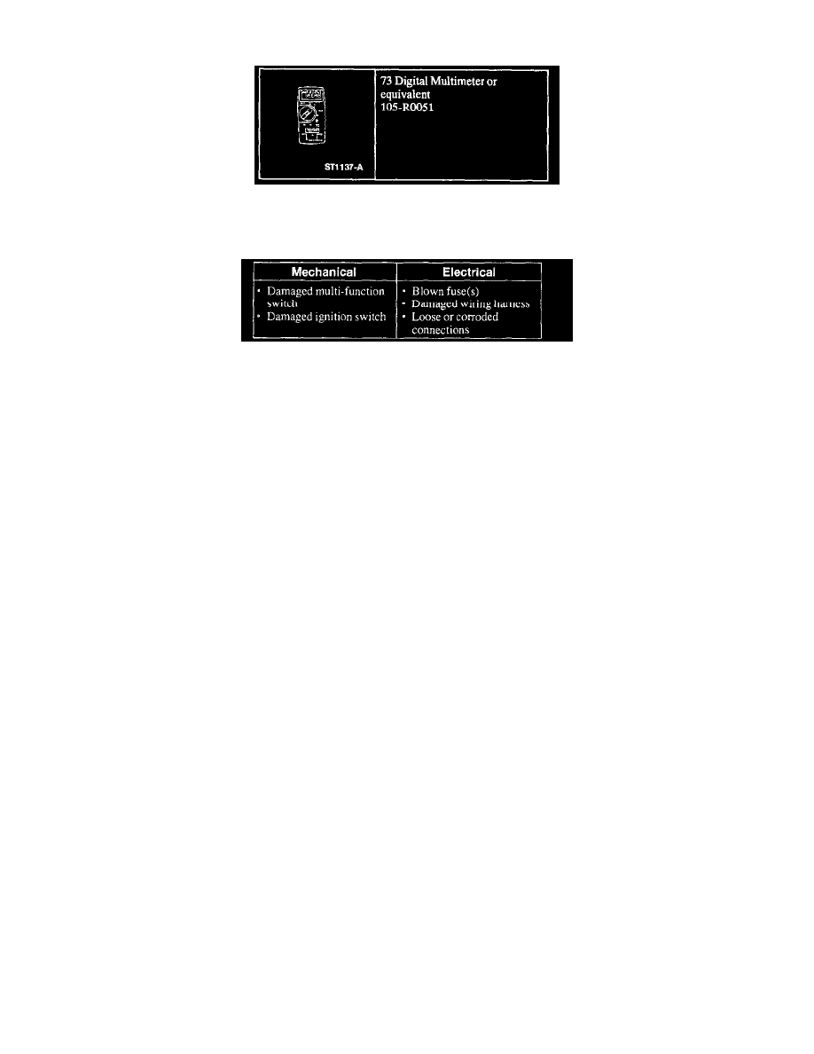
73 Digital Multimeter
1. Verify the customer concern by operating the multi-function or ignition switch.
Visual Inspection Chart
2. Visually inspect for obvious signs of mechanical and electrical damage.
3. If the concern remains after the inspection connect the New Generation STAR (NGS) Tester to the data link connector (DLC) located beneath the
instrument panel and select the vehicle to be tested from the NGS menu. If the NGS does not communicate with the vehicle:
-
check that the program card is properly installed.
-
check the connections to the vehicle.
-
check the ignition switch position.
4. If the NGS still does not communicate with the vehicle, refer to the New Generation STAR Tester manual.
5. Perform the DATA LINK DIAGNOSTIC TEST.
If the NGS responds with:
-
CKT914, CKT915 or CKT7 = ALL ECUS NO RESP/NOT EQUIP, Diagnose the Module Communications Network.
-
NO RESP/NOT EQUIP for GEM/CTM, go to Pinpoint Test E. See: Pinpoint Tests
-
SYSTEM PASSED, retrieve and record the continuous diagnostic trouble codes (DTCs), erase the continuous DTCs and perform self-test
diagnostics for the GEM/CTM.
6. If the DTCs retrieved are related to the concern, go to GEM/CTM Diagnostic Trouble Code (DTC) Index to continue diagnostics. See: Diagnostic
Trouble Code Descriptions/GEM/CTM Diagnostic Trouble Code (DTC) Index
7. If no DTCs related to the concern are retrieved, proceed to Symptom Chart to continue diagnostics. See: Symptom Related Diagnostic Procedures