
Ranger 4WD V6-3.0L VIN V Flex Fuel (1999)
Information Bus: Testing and Inspection
Module Communication Network
Inspection and Verification (Start Here)
1. Verify the customer concern.
2. Visually inspect for obvious signs of electrical damage. Refer to the following chart:
VISUAL INSPECTION CHART
Electrical
^
Central Junction Box (CJB) Fuse 5 (10 A).
^
Damaged wiring harness
^
Loose or corroded connectors
^
4-wheel anti-lock brake control module
^
Restraint Control Module (RCM)
^
Generic Electronic Module (GEM)/Central Timer Module (CTM)
^
Passive Anti-Theft System (PATS) module
^
Powertrain Control Module (PCM)
^
Remote Anti-theft Personality (RAP) module
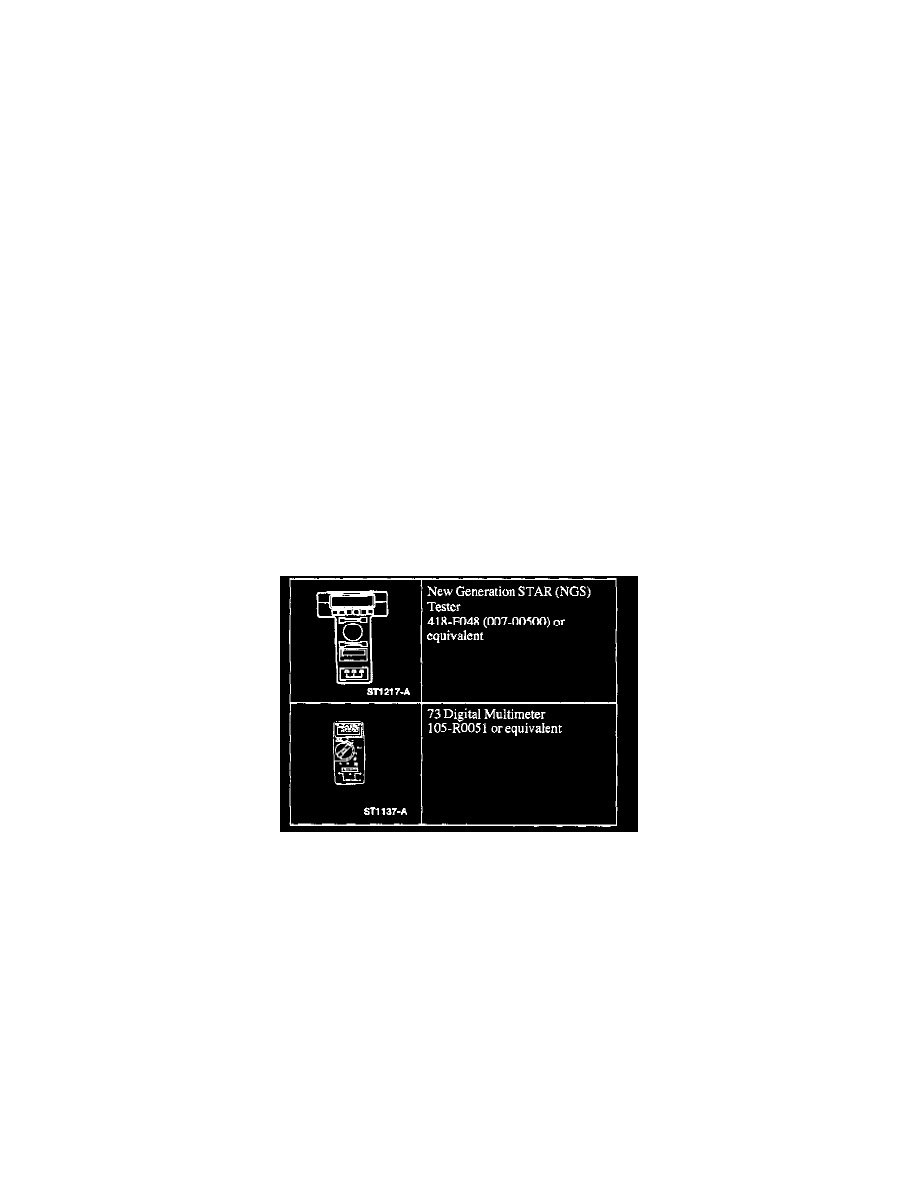
3. If the concern remains after the inspection, connect the New Generation STAR (NGS) Tester to the Data Link Connector (DLC) located beneath
the instrument panel and select the vehicle to be tested from the NOS Tester menu. If the NGS Tester does not communicate with the vehicle:
^
Check that the program card is properly installed.
^
Check the connections to the vehicle.
^
Check the ignition switch is in RUN. If NGS Tester still does not communicate with the vehicle, go to Pinpoint Test I. See: Pinpoint Tests/I:
No Module/Network Communication - No Power to the NGS
4. Go to Pinpoint Test PC. See: System Precheck
Diagnostic Schematic and Connector Information
Refer to Vehicle/Diagrams for schematic and connector information. See: Diagrams
Principles of Operation (How Does It Work?)
The vehicle has two module communications networks. The Standard Corporate Protocol (SCP) which is an unshielded twisted pair cable (data bus plus,
Circuit 914 [TN/OG] and data bus minus, Circuit 915 [PK/LB]), and the International Standards Organization (ISO) 9141 network which is a single wire
(Circuit 70 [LB/WH]). The New Generation STAR (NGS) Tester can connect to both networks through the Data Link Connector (DLC). This makes
diagnosis and testing of these systems easier by allowing one smart tester to be able to diagnose and control any module on the two networks from one
connector. The DLC can be found under the instrument panel between the steering column and the radio.
The ISO 9141 communication network does not permit inter-module communication. When the NGS Tester communicates to modules on the ISO 9141
communication network, the NGS Tester must ask for all information; the modules cannot initiate communications.
The SCP communication network will remain operational even with the severing of one of the bus wires. Communications will also continue if one of the
bus wires is shorted to ground or battery positive voltage (B+) or if some, but not all, termination resistors are lost.
Unlike the SCP communication network, the ISO 9141 communication network will not function if the wire is shorted to chassis ground or battery
positive voltage (B+). Also, if one of the modules on the ISO 9141 network loses power or shorts internally, communications to that module will fail.
The Powertrain Control Module (PCM) is on the SCP communication network. The PCM controls the engine for better fuel economy, emissions