
Ranger 4WD V6-4.0L (2009)
J5 CHECK THE MS-CAN (+) AND MS-CAN (-) CIRCUITS FOR A SHORT TO GROUND
-
Measure the resistance between the DLC C251-3, circuit VDB06 (GY/OG), harness side and ground; and between the DLC C251-11, circuit
VDB07 (VT/OG), harness side and ground.
-
Are the resistances greater than 5,000 ohms?
Yes
GO to J6.
No
GO to J12.
-------------------------------------------------
J6 CHECK THE MS-CAN (+) AND MS-CAN (-) CIRCUITS FOR A SHORT TO VOLTAGE
-
Connect the vehicle battery.
-
Ignition ON.
-
Measure the voltage between the DLC C251-3, circuit VDB06 (GY/OG), harness side and ground; and between the DLC C251-11, circuit VDB07
(VT/OG), harness side and ground.
-
Are the voltages greater than 6 volts?
Yes
REPAIR the circuit. CLEAR the DTCs. REPEAT the network test with the scan tool.
No
GO to J7.
-------------------------------------------------
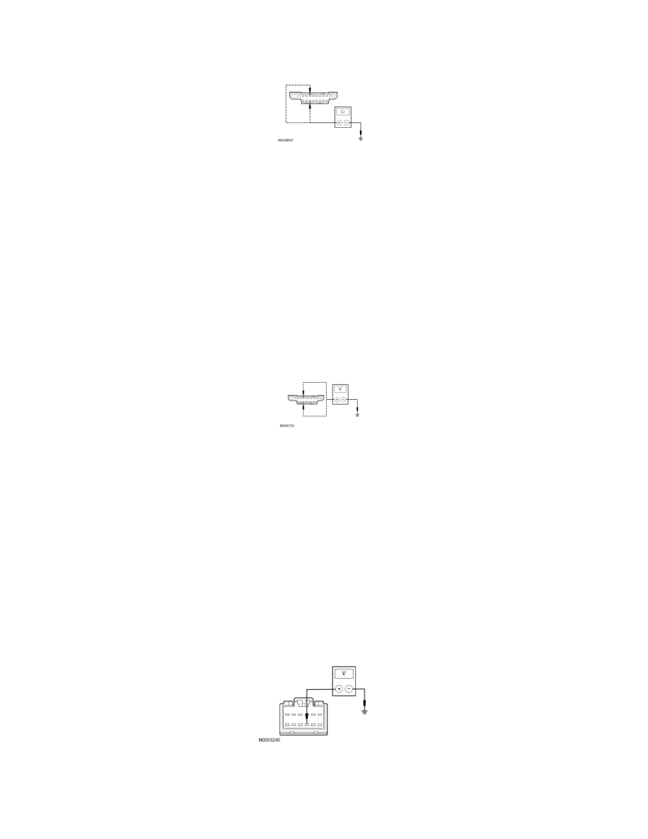
J7 CHECK THE SDARS MODULE VOLTAGE SUPPLY CIRCUITS FOR AN OPEN
-
Ignition OFF.
-
Disconnect: SDARS Module C2358.
-
Ignition ON.
-
Measure the voltage between the SDARS module C2358-9, circuit SBP12 (GN/RD), harness side and ground.
-
Are the voltages greater than 10 volts?
Yes