
Ranger 4WD V6-4.0L (2009)
Driveshaft Inspection
NOTE: Driveline vibration exhibits a higher frequency and lower amplitude than high-speed shake. Driveline vibration is directly related to the speed of
the vehicle and is noticed at various speeds. Driveline vibration can be perceived as a tremor in the floorpan or heard as a rumble, hum or boom.
NOTE: Refer to Specifications for all runout specifications.
1. NOTE: Do not make any adjustments before carrying out a road test. Do not change the tire pressure or the vehicle load. See: Testing and
Inspection/Symptom Related Diagnostic Procedures/5: Road Test
Carry out a visual inspection of the vehicle. Operate the vehicle and verify the condition by reproducing it during the road test.
-
The concern should be directly related to vehicle road speed, not affected by acceleration or deceleration or could not be reduced by coasting
in NEUTRAL.
2. With the vehicle in NEUTRAL, position it on a hoist.
-
The driveshaft should be kept at an angle equal to or close to the curb-weighted position. Use a twin-post hoist or a frame hoist with
jackstands.
3. Inspect the driveshaft for damage, undercoating or incorrectly seated U-joints. Rotate the driveshaft slowly by hand and feel for binding or end
play in the U-joint trunnions. Remove the driveshaft. Inspect the slip yoke splines for any galling, dirt, rust or incorrect lubrication. Clean the
driveshaft or install new U-joints as necessary. Install a new driveshaft if damaged. After any corrections or new components are installed, recheck
for the vibration at the road test speed.
-
If the vibration is gone, test drive the vehicle.
-
If the vibration persists or the driveshaft passes visual inspection, measure the driveshaft runout.
Driveshaft Runout
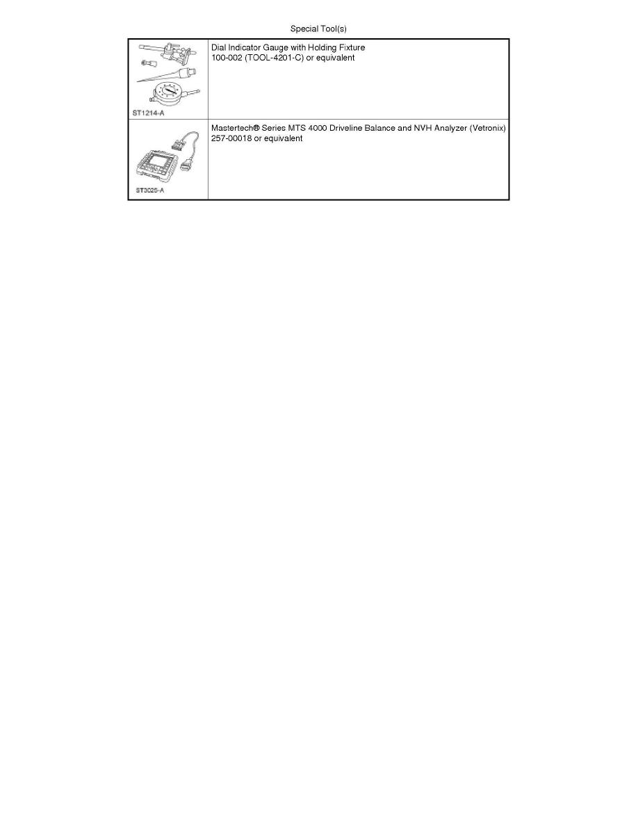
1. Install the Dial Indicator Gauge with Holding Fixture. Rotate the driveshaft by turning the axle and measure the runout at the front, the center and
the rear of the driveshaft.
-
If the runout exceeds 1 mm (0.040 in) at the front or center, install a new driveshaft.
-
If the front and center is within 1 mm (0.040 in), but the rear runout is not, index-mark the rear runout high point and proceed to Step 2.
-
If the runout is within 1 mm (0.040 in) at all points, recheck for vibration at road test speed. If the vibration persists, balance the driveshaft.
For additional information, refer to Driveshaft Balancing in this procedure.
2. NOTE: Circular pinion flanges can be turned in 90 degree or one-fourth increments. Half-round pinion flanges are limited to 2 positions.
Index-mark the driveshaft to the pinion flange. Disconnect the driveshaft and rotate it 180 degrees. Reconnect the driveshaft. Recheck the runout at
the rear of the driveshaft.
-
If the runout is still over specification, mark the high point and proceed to Step 3.
-
If the runout is within specification, check for the vibration at the road test speed. If the vibration is still present, balance the driveshaft. For
additional information, refer to Driveshaft Balancing in this procedure.
3. Excessive driveshaft runout can originate in the driveshaft itself or from the pinion flange. To find the source, compare the 2 high points