| Diagnosis and Testing Refer to Wiring Diagrams Section 412-02, for schematic and connector information. Special Tool(s) | | Terminal Probe Kit 418-S035 | General Equipment Digital Multimeter (compatible with K-type thermocouple) Thermometer - Fluke 80 PK-8 (FSE number 260 4102 001 07) Worldwide Diagnostic System (WDS) Refrigerant center Inspection and Checking - Visually CHECK for any obvious mechanical or electrical damage.
Visual Inspection | Mechanical | Electrical | - Refrigerant lines
- Condenser core
- Drive belt
- Coolant level
- Coolant hose(s)
| - Fuses
- Wiring harness
- Connectors
| - RECTIFY any obvious causes for a concern found during the visual inspection before performing any further tests. CHECK the operation of the system.
- If the concern persists after the visual inspection, PERFORM a fault diagnosis on the electronic engine management with WDS and RECTIFY any displayed faults in accordance with the displayed fault description. CHECK the operation of the system.
- For vehicles with no stored faults, PROCEED in accordance with the Symptom Chart according to the fault symptom.
- Following checking or elimination of the fault and after completion of operations, the fault memories of all vehicle modules must be READ OUT and any stored faults must be DELETED. READ OUT all fault memories again following a road test.
Symptom Chart | Symptom | Possible Sources | Action | | Temperature control faulty / inoperative | * Fuse(s) * Circuit(s) * Heater control module * Heater control valve * Cooling system * Powertrain control module (PCM) * Instrument cluster | * | | Blower faulty / inoperative | * Fuse(s) * Circuit(s) * Blower * Blower switch * Blower resistor assembly | * | | Blower running continuously | * Circuit(s) * Blower switch | * | | Air conditioning inoperative (blower and heater OK) | * Fuse(s) * Circuit(s) * Air conditioning clutch * A/C clutch diode * A/C clutch relay * A/C relay * Refrigerant low-pressure switch * Refrigerant high-pressure switch * Heater control module * Powertrain control module (PCM) * Refrigerant quantity | * | | Inadequate A/C output | * Engine cooling fans * Condenser core * Refrigerant circuit * Refrigerant quantity * Refrigerant line * Accumulator/dehydrator * Air Conditioning (A/C) Compressor * Fixed orifice tube | * CHECK cooling fans with WDS. * CHECK refrigerant circuit. | | Malfunction of the air recirculation flap - vehicles with A/C (heater and A/C OK) | * Circuit(s) * Air flap actuator * Heater control module | * Vehicles built up to 1/1999: GO to Pinpoint Test E. * Vehicles built from 01/1999: GO to Pinpoint Test F. | | Condensed water from the air conditioning system in the footwell | * Outlet line * Rubber grommet | * CHECK condition of the outlet line and the rubber grommet and REPAIR if necessary. | Refrigerant Circuit - Quick Check WARNING:The air conditioning system is filled with refrigerant R134a. Observe "Health and Safety Precautions". For further information
REFER to: Gesundheits- und Sicherheitsvorkehrungen (100-00, Description and Operation).
Refrigerant circuit check WARNING:Under certain circumstances, refrigerant lines and A/C components may be extremely hot or cold. Exercising care, touch the refrigerant lines or A/C components in order to check this. Failure to observe this instruction can lead to injury. - The refrigerant line from the refrigerant compressor to the condenser must be hot.
- The refrigerant line from the A/C condenser to the fixed orifice tube must be warm, but not so hot as the refrigerant line mentioned above.
- Determine the difference in temperature upstream and downstream of the A/C condenser by measuring the temperatures. Depending on the ambient temperature, the temperature difference should be more than 20°. If the temperature difference is less, check the condenser for contamination or damage to the fins as well as operation of the radiator fans.
- The refrigerant line between the fixed orifice tube and the evaporator must be cold from the point where the fixed orifice tube is installed. Depending on the weather, the refrigerant line may also have ice on its surface.
- The refrigerant line between the evaporator and the A/C compressor including the dehydrator must be cold.
Evaporator outlet temperature test To test the power of the A/C system, the temperature of the evaporator outlet line must be measured. To do this, the following preconditions must be met: - Open all windows.
- Set the air distribution to the defrost/dashboard position and open all the ventilation nozzles.
- DO NOT switch on recirculated air.
- Select lowest blower switch setting.
- Select lowest temperature setting.
NOTE:The temperature measurement cannot be done with a thermometer which makes no contact. False measurements may arise as a result of surface reflections. Connect the temperature sensor (Fluke 80 PK-8) to the outlet side of the evaporator. The temperature sensor must be positioned as closely as possible to the evaporator. Connect the temperature sensor to the multimeter. Start the engine and allow it to run at idle speed for several minutes. Switch on the air-conditioning system. After three minutes, measure the surface temperature of the evaporator outlet line. If the temperature measured is 2° C or lower, the A/C system is OK. If the temperature is higher, the A/C system may be under-filled. For further information, refer to
REFER to: Klimaanlage entleeren, evakuieren und befüllen (412-00, General Procedures).
Frequent faults and their causes If the customer expresses concern about insufficient cooling performance, ensure that the temperature control is working properly. - No or poor cooling performance:
- Blockage or restriction in one of the refrigerant lines or in the dehydrator: By comparing temperatures at the refrigerant lines or at the dehydrator, the location of the blockage or restriction can easily be identified. The blockage or restriction is located at the point where the temperature difference is identified. Note: A temperature difference in the area of the fixed orifice tube is normal. Once the location of the blockage or restriction has been detected, check the relevant component and renew if necessary. - Sudden poor cooling performance. After the compressor has been switched off for approx. 5 minutes, the cooling performance returns to normal:
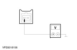
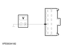
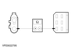
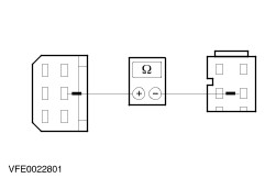
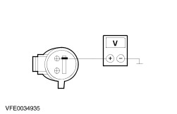
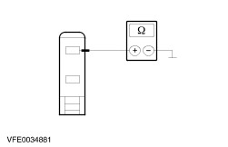
- Fixed orifice tube iced up. The cause for an iced-up fixed orifice tube is moisture in the refrigerant circuit. In order to ensure that moisture is completely removed from the refrigerant circuit, evacuation time must be extended to 2-3 hours and the dehydrator must be renewed. For further information REFER to: Trockner (412-03, Removal and Installation), Klimaanlage entleeren, evakuieren und befüllen (412-00, General Procedures). System Checks | PINPOINT TEST A : TEMPERATURE CONTROL FAULTY / INOPERATIVE | NOTE:The heater control valve reacts with delay to changes to the temperature settings. | | TEST CONDITIONS | DETAILS/RESULTS/ACTIONS | | A1: DETERMINE THE FAULT CONDITIONS | | | 1 Ignition switch in position III. | | | 2 Run the engine until the temperature gauge indicates "NORMAL". | | | 3 Check operation of heater. | | | Does the heater continuously supply cold air? Yes No | | A2: CHECK HEATER CONTROL VALVE | WARNING:Never perform operations on the heater control valve before the heater control valve has cooled to ambient temperature. Failure to observe this instruction can lead to injury. | | | 1 Set the temperature control to medium temperature. | | | 2 Check whether the heater control valve pulsates. | | | Is the heater control valve pulsating? Yes CHECK the coolant hoses for correct routing. BLEED the cooling system if necessary. If the cooling system is OK, RENEW the heater control valve. CHECK the operation of the system. No | | A3: CHECK THE VOLTAGE AT THE HEATER CONTROL VALVE | | | 1 Ignition switch in position 0. | | | 2 Disconnect connector C42 from heater control valve. | | | 3 Ignition switch in position II. | | | 4 Measure the voltage between the heater control valve, connector C42, pin 1, circuit 14-CA82 (VT/BK), wiring harness side and ground. | | | Does the meter display battery voltage? Yes No LOCATE and REPAIR the break in circuit 14-CA82 (VT/BK) between the heater control valve and soldered connection S6 using the Wiring Diagrams. CHECK the operation of the system. | | A4: CHECK HEATER CONTROL VALVE | | | 1 Ignition switch in position 0. | | | 2 Measure the resistance at the heater control valve, connector C42, between pin 1 and pin 2, component side. | | | Is a resistance of 10-25 Ohms measured? Yes No RENEW the heater control valve. CHECK the operation of the system. | | A5: CHECK CONTROL VOLTAGE AT HEATER CONTROL VALVE | | | 1 Ignition switch in position III. 2 Run the engine at idle speed. | | | 3 Set the temperature control to medium temperature. | | | 4 Measure the voltage between the heater control valve, connector C42, pin 1, circuit 14-CA82 (VT/BK), wiring harness side and pin 2, circuit 31S-CA82 (BK/GN), wiring harness side. | | | Is an intermittent voltage between 0 V and battery voltage measured? Yes RENEW the heater control valve. CHECK the operation of the system. No | | A6: CHECK THE VOLTAGE AT THE HEATER CONTROL MODULE | | | 1 Ignition switch in position 0. | | | 2 Disconnect connector C41 from heater control module. | | | 3 Ignition switch in position II. | | | 4 Measure the voltage between the heater control module, connector C41, pin 8, circuit 14-CA83 (vehicles with 1.3L or 1.6L Duratec-8V (Rocam) engine: 14-CA83A) (VT/OG), wiring harness side and ground. | | | Does the meter display battery voltage? Yes No LOCATE and REPAIR the break in the circuit between the heater control module and fuse F17 using the Wiring Diagrams. CHECK the operation of the system. | | A7: CHECK THE VOLTAGE AT THE HEATER CONTROL MODULE | | | 1 Ignition switch in position 0. | | | 2 Measure the voltage between the heater control module, connector C41, pin 9, circuit 29-CA83 (OG/GN), wiring harness side and ground. | | | Does the meter display battery voltage? Yes No LOCATE and REPAIR the break in circuit 29-CA83 (OG/GN) between the heater control module and soldered connection S20 using the Wiring Diagrams. CHECK the operation of the system. | | A8: CHECK THE GROUND CONNECTION OF THE HEATER CONTROL MODULE | | | 1 Measure the resistance between the heater control module, connector C41, pin 2, circuit 91-CA83 (BK/RD), wiring harness side and ground. | | | Is a resistance of less than 2 Ohms registered? Yes No LOCATE and REPAIR the break in circuit 91-CA83 (BK/RD) between the heater control module and ground connection G4 using the Wiring Diagrams. CHECK the operation of the system. | | A9: CHECK FOR OPEN CIRCUIT BETWEEN THE HEATER CONTROL MODULE AND THE HEATER CONTROL VALVE. | | | 1 Measure the resistance between the heater control module, connector C41, pin 10, circuit 31S-CA82 (BK/GN), wiring harness side and the heater control valve, connector C42, pin 2, circuit 31S-CA82 (BK/GN), wiring harness side. | | | Is a resistance of less than 2 Ohms registered? Yes CHECK the heater control module and RENEW as necessary. CHECK the operation of the system. No LOCATE and REPAIR the break in circuit 31S-CA82 (BK/GN) between the heater control module and the heater control valve using the Wiring Diagrams. CHECK the operation of the system. | | A10: CHECK HEATER CONTROL VALVE | | | 1 Ignition switch in position 0. | | | 2 Disconnect connector C42 from heater control valve. | | | 3 Ignition switch in position III. 4 Run the engine at idle speed. | | | 5 Check operation of heater. | | | Does the heater become warm? Yes No CHECK the coolant hoses for correct routing. BLEED the cooling system if necessary. For further information REFER to: Kühlsystem entleeren, mit Kühlmittel auffüllen und entlüften (303-03A, General Procedures), Kühlsystem entleeren, mit Kühlmittel auffüllen und entlüften (303-03B, General Procedures). If the cooling system is OK, remove the heater control valve and CHECK for blockages; RENEW if necessary. CHECK the operation of the system. | | A11: CHECK THE CIRCUIT BETWEEN THE HEATER CONTROL MODULE AND THE HEATER CONTROL VALVE FOR A SHORT TO GROUND | | | 1 Ignition switch in position 0. | | | 2 Connect connector C42 to heater control valve. | | | 3 Disconnect connector C41 from heater control module. | | | 4 Ignition switch in position III. 5 Run the engine at idle speed. | | | 6 Check operation of heater. | | | Does the heater become warm? Yes No LOCATE and REPAIR the short to ground in circuit 31S-CA82 (BK/GN) between the heater control valve and the heater control module with the aid of the Wiring Diagrams. CHECK the operation of the system. | | A12: CHECK THE SPEED SIGNAL AT THE HEATER CONTROL MODULE | NOTE:If the speed signal at the heater control module is faulty, the heater cannot be set to "WARM". | | | NOTE:Perform measurement using WDS. Set the multimeter to "AC voltage" mode in order to measure the voltage. 1 Measure the voltage between the heater control module, connector C41, pin 6, circuit 8-GB10A (WH/BK), wiring harness side and ground. | | | Is a voltage of approx. 9 volts measured? Yes CHECK the heater control module and RENEW as necessary. CHECK the operation of the system. No - Vehicles with 1.3L Endura E (HCS) engine and 104-pin powertrain control module (PCM): GO to A13. - Vehicles with 1.0L or 1.3L Endura E (HCS) engine and 60-pin powertrain control module (PCM): GO to A14. - Vehicles with 1.3L or 1.6L Duratec 8V (Rocam) engine: GO to A15. | | A13: CHECK THE SIGNAL LINE BETWEEN THE HEATER CONTROL MODULE AND THE PCM - VEHICLES WITH 1.3L ENDURA E (HCS) ENGINE AND 104-PIN PCM: | | | 1 Ignition switch in position 0. | | | 2 Disconnect connector C159 from PCM. | | | 3 Measure the resistance between the heater control module, connector C41, pin 6, circuit 8-GB10A (WH/BK), wiring harness side and PCM, connector C159, pin 48, circuit 8-GB10A (WH/BK), wiring harness side. | | | Is a resistance of less than 2 Ohms registered? Yes CHECK the PCM and RENEW if necessary. CHECK the operation of the system. No LOCATE and REPAIR the open circuit between the heater control module and the PCM using the Wiring Diagrams. CHECK the operation of the system. | | A14: CHECK THE SIGNAL LINE BETWEEN THE HEATER CONTROL MODULE AND THE PCM - VEHICLES WITH 1.0 OR 1.3L ENDURA E (HCS) ENGINE AND 60-PIN PCM | | | 1 Ignition switch in position 0. | | | 2 Disconnect connector C1159 from PCM. | | | 3 Measure the resistance between the heater control module, connector C41, pin 6, circuit 8-GB10A (WH/BK), wiring harness side and PCM, connector C1159, pin 4, circuit 8-GB10A (WH/BK), wiring harness side. | | | Is a resistance of less than 2 Ohms registered? Yes CHECK the PCM and RENEW if necessary. CHECK the operation of the system. No LOCATE and REPAIR the open circuit between the heater control module and the PCM using the Wiring Diagrams. CHECK the operation of the system. | | A15: CHECK THE SIGNAL LINE BETWEEN THE HEATER CONTROL MODULE AND THE INSTRUMENT CLUSTER - VEHICLES WITH 1.3L OR 1.6L DURATEC 8V (ROCAM) ENGINE | | | 1 Ignition switch in position 0. | | | 2 Disconnect Connector C844 from instrument cluster. | | | 3 Measure the resistance between the heater control module, connector C41, pin 6, circuit 8-GB10A (WH/BK), wiring harness side and the instrument cluster, connector C844, pin 28, circuit 8-GB10A (WH/BK), wiring harness side. | | | Is a resistance of less than 2 Ohms registered? Yes CHECK and if necessary RENEW the instrument cluster. CHECK the operation of the system. No LOCATE and REPAIR the break in circuit 8-GB10A (WH/BK) between the heater control module and the instrument cluster using the Wiring Diagrams. CHECK the operation of the system. | | PINPOINT TEST B : BLOWER FAULTY / INOPERATIVE | | TEST CONDITIONS | DETAILS/RESULTS/ACTIONS | | B1: CHECK ALL SPEED SETTINGS OF THE BLOWER MOTOR | | | 1 Ignition switch in position II. | | | 2 Switch the blower switch through all speed settings. | | | Is the blower motor inoperative in all the switch positions? Yes No - The blower motor is inoperative in switch positions 1, 2 and/or 3: GO to B9. - The blower motor is only inoperative in switch position 4: GO to B8. | | B2: CHECK FUSE F12 | | | 1 Ignition switch in position 0. | | | 2 CHECK fuse F12 (CJB). | | | Is the fuse OK? Yes No RENEW fuse F12 (30 A). CHECK the operation of the system. If the fuse blows again, LOCATE and REPAIR the short using the Wiring Diagrams. | | B3: CHECK THE VOLTAGE SUPPLY AT FUSE F12 | | | 1 Connect fuse F12 (CJB). | | | 2 Ignition switch in position II. | | | 3 Measure the voltage between fuse F12 (30 A) and ground. | | | Does the meter display battery voltage? Yes No REPAIR the voltage supply to fuse F12 using the Wiring Diagrams. CHECK the operation of the system. | | B4: CHECK THE VOLTAGE AT THE BLOWER MOTOR | | | 1 Ignition switch in position 0. | | | 2 Disconnect Connector C221 from the blower motor. | | | 3 Ignition switch in position II. | | | 4 Measure the voltage between the blower motor, connector C221, pin 1, circuit 14-CA18 (VT/OG), wiring harness side and ground. | | | Does the meter display battery voltage? Yes No LOCATE and REPAIR the break in the circuit between the blower motor and fuse F12 using the Wiring Diagrams. CHECK the operation of the system. | | B5: CHECK THE GROUND CONNECTION OF THE BLOWER MOTOR | | | 1 Ignition switch in position 0. | | | 2 Set the blower switch to setting 4. | | | 3 Measure the resistance between the blower motor, connector C221, pin 2, circuit 31S-CA18 (BK/RD), wiring harness side and ground. | | | Is a resistance of less than 2 Ohms registered? Yes RENEW the blower motor. CHECK the operation of the system. No | | B6: CHECK THE CIRCUIT BETWEEN THE BLOWER MOTOR AND THE BLOWER SWITCH FOR OPEN CIRCUIT | | | 1 Disconnect Connector C38 from the blower switch. | | | 2 Measure the resistance between the blower motor, connector C221, pin 2, circuit 31S-CA18 (BK/RD), wiring harness side and the blower switch, connector C38, pin 4, circuit 31S-CA33 (BK/OG), wiring harness side. | | | Is a resistance of less than 2 Ohms registered? Yes No LOCATE and REPAIR the break in circuit 31S-CA18 (BK/RD) between the blower motor and soldered connection S88 using the Wiring Diagrams. CHECK the operation of the system. | | B7: CHECK THE GROUND CONNECTION OF THE BLOWER SWITCH | | | 1 Measure the resistance between the blower switch, connector C38, pin 6, circuit 31-CA25 (BK), wiring harness side and ground. | | | Is a resistance of less than 2 Ohms registered? Yes RENEW the blower switch. CHECK the operation of the system. No LOCATE and REPAIR the break in the circuit between the blower switch and ground connection G6 using the Wiring Diagrams. CHECK the operation of the system. | | B8: CHECK THE CIRCUIT BETWEEN THE BLOWER MOTOR AND THE BLOWER SWITCH FOR OPEN CIRCUIT | | | 1 Ignition switch in position 0. | | | 2 Disconnect Connector C38 from the blower switch. | | | 3 Disconnect Connector C221 from the blower motor. | | | 4 Measure the resistance between the blower motor, connector C221, pin 2, circuit 31S-CA18 (BK/RD), wiring harness side and the blower switch, connector C38, pin 4, circuit 31S-CA33 (BK/OG), wiring harness side. | | | Is a resistance of less than 2 Ohms registered? Yes RENEW the blower switch. CHECK the operation of the system. No LOCATE and REPAIR the break in circuit 31S-CA33 (BK/OG) between soldered connection S88 and the blower switch using the Wiring Diagrams. CHECK the operation of the system. | | B9: CHECK THE BLOWER SWITCH | | | 1 Ignition switch in position 0. | | | 2 Disconnect Connector C38 from the blower switch. | | | 3 Ignition switch in position II. | | | 4 Measure the voltage between the blower switch, connector C38, pin 3, circuit 31S-CA30 (BK/WH), wiring harness side and ground. | | | 5 Measure the voltage between the blower switch, connector C38, pin 2, circuit 31S-CA31 (BK/YE), wiring harness side and ground. | | | 6 Measure the voltage between the blower switch, connector C38, pin 1, circuit 31S-CA32 (BK/BU), wiring harness side and ground. | | | Is battery voltage measured in all cases? Yes RENEW the blower switch. CHECK the operation of the system. No - Battery voltage not measured in any case: GO to B10. - Battery voltage not measured in one/two case(s): GO to B11. | | B10: CHECK THE VOLTAGE AT THE BLOWER RESISTOR ASSEMBLY | | | 1 Ignition switch in position 0. | | | 2 Disconnect Connector C220 from the blower resistor assembly. | | | 3 Ignition switch in position II. | | | 4 Measure the voltage between the blower resistor assembly, connector C220, pin 1, circuit 31S-CA18A (BK/RD), wiring harness side and ground. | | | Does the meter display battery voltage? Yes RENEW the blower resistor assembly. CHECK the operation of the system. No LOCATE and REPAIR the break in circuit 31S-CA18 (BK/RD) between the blower resistor assembly and soldered connection S88 using the Wiring Diagrams. CHECK the operation of the system. | | B11: CHECK THE CIRCUIT BETWEEN THE BLOWER RESISTOR ASSEMBLY AND THE BLOWER SWITCH FOR OPEN CIRCUIT | | | 1 Ignition switch in position 0. | | | 2 Disconnect Connector C220 from the blower resistor assembly. | | | 3 Measure the resistance between the blower resistor assembly, connector C220, pin 4, circuit 31S-CA32 (BK/BU), wiring harness side and the blower switch, connector C38, pin 1, circuit 31S-CA32 (BK/BU), wiring harness side. | | | 4 Measure the resistance between the blower resistor assembly, connector C220, pin 2, circuit 31S-CA31 (BK/YE), wiring harness side and the blower switch, connector C38, pin 2, circuit 31S-CA31 (BK/YE), wiring harness side. | | | 5 Measure the resistance between the blower resistor assembly, connector C220, pin 3, circuit 31S-CA30 (BK/WH), wiring harness side and the blower switch, connector C38, pin 3, circuit 31S-CA30 (BK/WH), wiring harness side. | | | Is a resistance of less than 2 Ohms measured in all of the cases? Yes RENEW the blower resistor assembly. CHECK the operation of the system. No LOCATE and REPAIR the break in the relevant circuit between the blower resistor assembly and the blower switch using the Wiring Diagrams. CHECK the operation of the system. | | PINPOINT TEST C : BLOWER RUNNING CONTINUOUSLY | | TEST CONDITIONS | DETAILS/RESULTS/ACTIONS | | C1: CHECK THE BLOWER SWITCH | | | 1 Ignition switch in position 0. | | | 2 Disconnect Connector C38 from the blower switch. | | | 3 Ignition switch in position II. | | | 4 Check the operation of the blower. | | | Does the blower run continuously? Yes No RENEW the blower switch. CHECK the operation of the system. | | C2: CHECK THE CIRCUITS AT THE BLOWER RESISTOR ASSEMBLY FOR A SHORT CIRCUIT TO GROUND | | | 1 Ignition switch in position 0. | | | 2 Disconnect Connector C220 from the blower resistor assembly. | | | 3 Ignition switch in position II. | | | 4 Check the operation of the blower. | | | Does the blower run continuously? Yes CHECK all circuits that are connected to soldered connection S88 for a short to ground using the Wiring Diagrams and REPAIR any short circuit(s) found. CHECK the operation of the system. No CHECK all circuits between the blower resistor assembly and the blower switch (vehicles with air conditioning system: additionally circuit 31S-CA25 (BK/GN) between the blower switch and the heater control module) for short circuit to ground using the Wiring Diagrams and REPAIR. CHECK the operation of the system. | | PINPOINT TEST D : AIR CONDITIONING INOPERATIVE (BLOWER AND HEATER OK) | | TEST CONDITIONS | DETAILS/RESULTS/ACTIONS | | D1: DETERMINE THE FAULT CONDITION | | | 1 Ignition switch in position III. | | | 2 Set the blower switch to position 1. | | | 3 Switch on the air-conditioning system. | | | Does the air conditioning clutch work? Yes - All vehicles:Perform a Quick Check of the refrigerant circuit.- Vehicles built up to 10/2002, additionally:Test the refrigerant circuit. See "Testing the Refrigerant Circuit" at the end of this section. No | | D2: CHECK THE CONTROL VOLTAGE AT THE AIR CONDITIONING CLUTCH RELAY | | | 1 Ignition switch in position 0. | | | 2 Disconnect A/C clutch relay C165. | | | 3 Ignition switch in position II. | | | 4 Measure the voltage between the A/C clutch relay, socket C165, pin 1, circuit 94S-CA11 (VT/YE), wiring harness side and ground. | | | Does the meter display battery voltage? Yes No LOCATE and REPAIR the break in circuit 94S-CA11 (VT/YE) between the A/C clutch relay and soldered connection S7 using the Wiring Diagrams. CHECK the operation of the system. | | D3: CHECK THE VOLTAGE AT THE AIR CONDITIONING CLUTCH RELAY | | | 1 Measure the voltage between the A/C clutch relay, socket C165, pin 5, circuit 14S-CA12 (VT/BU), wiring harness side and ground. | | | Does the meter display battery voltage? Yes No - All, except vehicles with 1.3L or 1.6L Duratec 8V (Rocam) engine: GO to D4. - Vehicles with 1.3L or 1.6L Duratec 8V (Rocam) engine: GO to D6. | | D4: CHECK THE VOLTAGE AT THE REFRIGERANT HIGH-PRESSURE SWITCH - ALL, EXCEPT VEHICLES WITH 1.3L OR 1.6L DURATEC 8V (ROCAM) ENGINE | | | 1 Ignition switch in position 0. | | | 2 Disconnect Connector C96 from the refrigerant high-pressure switch. | | | 3 Ignition switch in position II. | | | 4 Vehicles built up to 11/2001: - Measure the voltage between the refrigerant high-pressure switch, connector C96, pin 2, circuit 14-CA38 (VT), wiring harness side and ground.
| | | 5 Vehicles built from 11/2001 to 01/2002: - Measure the voltage between the refrigerant high-pressure switch, connector C96, pin 2, circuit 14-CA38 (VT), wiring harness side and ground.
| | | 6 Vehicles built from 01/2002: - Measure the voltage between the refrigerant high-pressure switch, connector C96, pin 1, circuit 14-CA38 (VT), wiring harness side and ground.
| | | Does the meter display battery voltage? Yes No LOCATE and REPAIR the break in circuit 14-CA38 (VT) between the refrigerant high-pressure switch and soldered connection S6 using the Wiring Diagrams. CHECK the operation of the system. | | D5: CHECK THE REFRIGERANT HIGH-PRESSURE SWITCH - ALL, EXCEPT VEHICLES WITH 1.3L OR 1.6L DURATEC 8V (ROCAM) ENGINE | | | 1 Ignition switch in position 0. | | | 2 Vehicles built up to 11/2001: - Measure the resistance at the refrigerant high-pressure switch, connector C96, between pin 2 and pin 4, component side.
| | | 3 Vehicles built from 11/2001 to 01/2002: - Measure the resistance at the refrigerant high-pressure switch, connector C96, between pin 2 and pin 4, component side.
| | | 4 Vehicles built from 01/2002: - Measure the resistance at the refrigerant high-pressure switch, connector C96, between pin 1 and pin 4, component side.
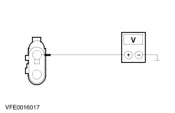
| | | Is a resistance of less than 2 Ohms registered? Yes LOCATE and REPAIR the break in the circuit between the air conditioning clutch relay and the refrigerant high-pressure switch using the Wiring Diagrams. CHECK the operation of the system. No RENEW the refrigerant high-pressure switch. CHECK the operation of the system. | | D6: CHECK THE VOLTAGE AT THE REFRIGERANT HIGH-PRESSURE SWITCH - VEHICLES WITH 1.3L OR 1.6L DURATEC 8V (ROCAM) ENGINE | | | 1 Ignition switch in position 0. | | | 2 Disconnect Connector C896 from the refrigerant high-pressure switch. | | | 3 Ignition switch in position II. | | | 4 Measure the voltage between the refrigerant high-pressure switch, connector C896, pin 1, circuit 14-CA38 (VT), wiring harness side and ground. | | | Does the meter display battery voltage? Yes No LOCATE and REPAIR the break in circuit 14-CA38 (VT) between the refrigerant high-pressure switch and soldered connection S6 using the Wiring Diagrams. CHECK the operation of the system. | | D7: CHECK THE REFRIGERANT HIGH-PRESSURE SWITCH - VEHICLES WITH 1.3L OR 1.6L DURATEC 8V (ROCAM) ENGINE | | | 1 Ignition switch in position 0. | | | 2 Measure the resistance at the refrigerant high-pressure switch, connector C896, between pin 1 and pin 4, component side. | | | Is a resistance of less than 2 Ohms registered? Yes LOCATE and REPAIR the break in the circuit between the air conditioning clutch relay and the refrigerant high-pressure switch using the Wiring Diagrams. CHECK the operation of the system. No RENEW the refrigerant high-pressure switch. CHECK the operation of the system. | | D8: CHECK THE CIRCUIT OF THE A/C CLUTCH | | | 1 Ignition switch in position 0. | | | 2 Use a fused test cable (10 A) at the A/C clutch relay, socket C165, to jumper pin 3, circuit 14S-CA12 (VT/BU), wiring harness side and pin 5, circuit 14S-CA1 (VT/BU), wiring harness side. | | | 3 Ignition switch in position II. | | | Does the air conditioning clutch work? Yes No | | D9: CHECK THE VOLTAGE AT THE A/C CLUTCH | | | 1 Ignition switch in position 0. | | | 2 Disconnect Connector C94 from the A/C clutch. | | | 3 Use a fused test cable (10 A) at the A/C clutch relay, socket C165, to jumper pin 3, circuit 14S-CA12 (VT/BU), wiring harness side and pin 5, circuit 14S-CA1 (VT/BU), wiring harness side. | | | 4 Ignition switch in position II. | | | 5 - All, except vehicles with 1.3L or 1.6L Duratec 8V (Rocam) engine: - Measure the voltage between the A/C clutch, connector C94, pin 2, circuit 14S-CA6 (VT/YE) (vehicles built up to 01:2000: circuit 14S-LA6), wiring harness side and ground.
| | | 6 - Vehicles with 1.3L or 1.6L Duratec 8V (Rocam) engine: - Measure the voltage between the A/C clutch, connector C94, pin 2, circuit 14S-CA6 (VT/YE), wiring harness side and ground.
| | | Does the meter display battery voltage? Yes No LOCATE and REPAIR the break in the circuit between the air conditioning clutch relay and the air conditioning clutch using the Wiring Diagrams. CHECK the operation of the system. | | D10: CHECK THE GROUND CONNECTION OF THE A/C CLUTCH | | | 1 Ignition switch in position 0. | | | 2 - All, except vehicles with 1.3L or 1.6L Duratec 8V (Rocam) engine: - Measure the resistance between the A/C clutch, connector C94, pin 1, circuit 31-CA6 (BK), wiring harness side and ground.
| | | 3 - Vehicles with 1.3L or 1.6L Duratec 8V (Rocam) engine: - Measure the resistance between the A/C clutch, connector C94, pin 1, circuit 31-CA6 (BK), wiring harness side and ground.
| | | Is a resistance of less than 2 Ohms registered? Yes RENEW the air conditioning clutch. CHECK the operation of the system. No LOCATE and REPAIR the break in the circuit between the A/C clutch and ground connection G2. CHECK the operation of the system. | | D11: CHECK THE VOLTAGE AT THE REFRIGERANT LOW PRESSURE SWITCH | | | 1 Ignition switch in position 0. | | | 2 Disconnect Connector C95 from the refrigerant low-pressure switch. | | | 3 Ignition switch in position II. | | | 4 Set the blower switch to position 1. | | | 5 Switch on the air-conditioning system. | | | 6 Measure the voltage between the refrigerant low-pressure switch, connector C95, pin 4, circuit 14S-CA17 (VT/OG), wiring harness side and ground. | | | Does the meter display battery voltage? Yes No | | D12: CHECK THE REFRIGERANT LOW-PRESSURE SWITCH | | | 1 Ignition switch in position 0. | | | 2 Measure the resistance at the refrigerant low-pressure switch, connector C95, between pin 1 and pin 4, component side. | | | Is a resistance of less than 2 Ohms registered? Yes - Vehicles with 1.3L Endura E (HCS) engine and 104-pin powertrain control module (PCM): GO to D13. - Vehicles with 1.0L or 1.3L Endura E (HCS) engine and 60-pin powertrain control module (PCM): GO to D15. - Vehicles with 1.3L or 1.6L Duratec 8V (Rocam) engine: GO to D17. No CHECK the quantity of refrigerant.
REFER to: Klimaanlage entleeren, evakuieren und befüllen (412-00, General Procedures).
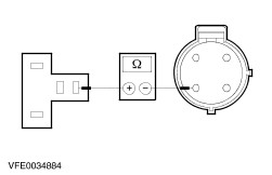
If the system is filled with the correct refrigerant quantity, RENEW the refrigerant low-pressure switch. CHECK the operation of the system. | | D13: CHECK THE CONTROL VOLTAGE AT THE POWERTRAIN CONTROL MODULE (PCM) - VEHICLES WITH 1.3L ENDURA E (HCS) ENGINE AND 104-PIN PCM | | | 1 Disconnect connector C159 from PCM. | | | 2 Connect Connector C95 to the refrigerant low-pressure switch. | | | 3 Ignition switch in position II. | | | 4 Set the blower switch to position 1. | | | 5 Switch on the air-conditioning system. | | | 6 Measure the voltage between the PCM, connector C159, pin 41, circuit 14S-PC72 (VT/BU), wiring harness side and ground. | | | Does the meter display battery voltage? Yes No LOCATE and REPAIR the break in circuit 14S-PC72 (VT/BU) between the refrigerant low-pressure switch and the PCM using the Wiring Diagrams. CHECK the operation of the system. | | D14: CHECK THE CIRCUIT BETWEEN THE A/C CLUTCH RELAY AND THE PCM FOR OPEN CIRCUIT - VEHICLES WITH 1.3L ENDURA E ENGINE AND 104-PIN PCM | | | 1 Measure the resistance between the air conditioning clutch relay, socket C165, pin 2, circuit 91S-CA11 (BK/YE), wiring harness side and the PCM, connector C159, pin 69, circuit 91S-CA11 (BK/YE), wiring harness side. | | | Is a resistance of less than 2 Ohms registered? Yes No LOCATE and REPAIR the break in circuit 91S-CA11 (BK/YE) between the air conditioning clutch relay and the PCM using the Wiring Diagrams. CHECK the operation of the system. | | D15: CHECK THE CONTROL VOLTAGE AT THE POWERTRAIN CONTROL MODULE (PCM) - VEHICLES WITH 1.0L OR 1.3L ENDURA E (HCS) ENGINE AND 60-PIN PCM | | | 1 Disconnect connector C1159 from PCM. | | | 2 Connect Connector C95 to the refrigerant low-pressure switch. | | | 3 Ignition switch in position II. | | | 4 Set the blower switch to position 1. | | | 5 Switch on the air-conditioning system. | | | 6 Measure the voltage between the PCM, connector C1159, pin 10, circuit 14S-PC72 (VT/BU), wiring harness side and ground. | | | Does the meter display battery voltage? Yes No LOCATE and REPAIR the break in circuit 14S-PC72 (VT/BU) between the refrigerant low-pressure switch and the PCM using the Wiring Diagrams. CHECK the operation of the system. | | D16: CHECK THE CIRCUIT BETWEEN THE A/C CLUTCH RELAY AND THE PCM FOR OPEN CIRCUIT - VEHICLES WITH 1.0L OR 1.3L ENDURA E (HCS) ENGINE AND 60-PIN PCM | | | 1 Measure the resistance between the air conditioning clutch relay, socket C165, pin 2, circuit 91S-CA11 (BK/YE), wiring harness side and the PCM, connector C1159, pin 54, circuit 91S-CA11 (BK/YE), wiring harness side. | | | Is a resistance of less than 2 Ohms registered? Yes No LOCATE and REPAIR the break in circuit 91S-CA11 (BK/YE) between the air conditioning clutch relay and the PCM using the Wiring Diagrams. CHECK the operation of the system. | | D17: CHECK THE VOLTAGE AT THE POWERTRAIN CONTROL MODULE (PCM) - VEHICLES WITH 1.3L OR 1.6L DURATEC 8V (ROCAM) ENGINE | | | 1 Disconnect connector C850 from PCM. | | | 2 Connect Connector C95 to the refrigerant low-pressure switch. | | | 3 Ignition switch in position II. | | | 4 Set the blower switch to position 1. | | | 5 Switch on the air-conditioning system. | | | 6 Measure the voltage between the PCM, connector C850, pin M40, circuit 14S-PC72 (VT/BU), wiring harness side and ground. | | | Does the meter display battery voltage? Yes No LOCATE and REPAIR the break in circuit 14S-PC72 (VT/BU) between the refrigerant low-pressure switch and the PCM using the Wiring Diagrams. CHECK the operation of the system. | | D18: CHECK THE CIRCUIT BETWEEN THE A/C CLUTCH RELAY AND THE PCM FOR OPEN CIRCUIT - VEHICLES WITH 1.3L OR 1.6L DURATEC 8V (ROCAM) ENGINE | | | 1 Measure the resistance between the air conditioning clutch relay, socket C165, pin 2, circuit 91S-CA11 (BK/YE), wiring harness side and the PCM, connector C850, pin M26, circuit 91S-CA11 (BK/YE), wiring harness side. | | | Is a resistance of less than 2 Ohms registered? Yes No LOCATE and REPAIR the break in circuit 91S-CA11 (BK/YE) between the air conditioning clutch relay and the PCM using the Wiring Diagrams. CHECK the operation of the system. | | D19: CHECK THE CIRCUIT BETWEEN THE AIR CONDITIONING CLUTCH RELAY AND THE PCM FOR SHORT TO VOLTAGE | | | 1 Ignition switch in position II. | | | 2 Measure the voltage between the A/C clutch relay, socket C165, pin 2, circuit 91S-CA11 (BK/YE), wiring harness side and ground. | | | Is a voltage measured? Yes No LOCATE and REPAIR the short to voltage in circuit 91S-CA11 (BK/YE) between the air conditioning clutch relay and the PCM using the Wiring Diagrams. CHECK the operation of the system. | | D20: CHECK THE A/C CLUTCH RELAY | | | 1 Check the A/C clutch relay according to the component test at the end of this section. | | | Is the A/C clutch relay OK? Yes CHECK the PCM and RENEW if necessary. CHECK the operation of the system. No RENEW the air conditioning clutch relay. CHECK and if necessary RENEW the air conditioning clutch diode. CHECK the operation of the system. | | D21: CHECK THE CIRCUIT BETWEEN THE A/C RELAY AND THE REFRIGERANT LOW-PRESSURE SWITCH FOR OPEN CIRCUIT. | | | 1 Ignition switch in position 0. | | | 2 Disconnect A/C relay C162 (CJB). | | | 3 Measure the resistance between the A/C relay, socket C162, pin 3, circuit 14S-CA17 (VT/OG), wiring harness side and the refrigerant low-pressure switch, connector C95, pin 4, circuit 14S-CA17 (VT/OG), wiring harness side. | | | Is a resistance of less than 2 Ohms registered? Yes - All, except vehicles with 1.3L or 1.6L Duratec 8V (Rocam) engine: GO to D22. - Vehicles with 1.3L or 1.6L Duratec 8V (Rocam) engine: GO to D23. No LOCATE and REPAIR the break in circuit 14S-CA17 (VT/OG) between the A/C relay and the refrigerant low-pressure switch using the Wiring Diagrams. CHECK the operation of the system. | | D22: CHECK THE CONTROL VOLTAGE AT THE A/C RELAY - ALL, EXCEPT VEHICLES WITH 1.3L OR 1.6L DURATEC 8V (ROCAM) ENGINE | | | 1 Ignition switch in position II. | | | 2 Measure the voltage between the A/C relay, socket C162, pin 2, circuit 14-CA66 (VT/OG), wiring harness side and ground. | | | Does the meter display battery voltage? Yes No LOCATE and REPAIR the break in circuit 14-CA66 (VT/OG) between the A/C relay and soldered connection S6 using the Wiring Diagrams. CHECK the operation of the system. | | D23: CHECK THE CONTROL VOLTAGE AT THE A/C RELAY - VEHICLES WITH 1.3L OR 1.6L DURATEC 8V (ROCAM) ENGINE | | | 1 Ignition switch in position II. | | | 2 Measure the voltage between the A/C relay, socket C162, pin 2, circuit 94S-CA66 (VT/OG), wiring harness side and ground. | | | Does the meter display battery voltage? Yes No LOCATE and REPAIR the break in circuit 94S-CA66 (VT/OG) between the A/C relay and soldered connection S7 using the Wiring Diagrams. CHECK the operation of the system. | | D24: CHECK THE VOLTAGE AT A/C RELAY | | | 1 Measure the voltage between the A/C relay, socket C162, pin 5, circuit 14S-CA67 (VT/BK), wiring harness side and ground. | | | Does the meter display battery voltage? Yes No LOCATE and REPAIR the break in circuit 14S-CA67 (VT/BK) between the A/C relay and the refrigerant high-pressure switch using the Wiring Diagrams. CHECK the operation of the system. | | D25: CHECK FOR OPEN CIRCUIT BETWEEN THE A/C RELAY AND THE HEATER CONTROL MODULE. | | | 1 Ignition switch in position 0. | | | 2 Disconnect connector C41 from heater control module. | | | 3 Measure the resistance between the A/C relay, socket C162, pin 1, circuit 31S-CA66 (BK/RD), wiring harness side and the heater control module, connector C41, pin 11, circuit 31S-CA66 (BK/RD), wiring harness side. | | | Is a resistance of less than 2 Ohms registered? Yes No LOCATE and REPAIR the break in circuit 31S-CA66 (BK/RD) between the A/C relay and the heater control module using the Wiring Diagrams. CHECK the operation of the system. | | D26: CHECK THE CIRCUIT BETWEEN THE A/C RELAY AND THE HEATER CONTROL MODULE FOR SHORT TO VOLTAGE SUPPLY | | | 1 Ignition switch in position II. | | | 2 Measure the voltage between the A/C relay, socket C162, pin 1, circuit 31S-CA66 (BK/RD), wiring harness side and ground. | | | Is a voltage measured? Yes LOCATE and REPAIR the short to voltage supply in circuit 31S-CA66 (BK/RD) between the A/C relay and the heater control module using the Wiring Diagrams. CHECK the operation of the system. No | | D27: CHECK THE VOLTAGE AT THE HEATER CONTROL MODULE | | | 1 Set the blower switch to position 0. | | | 2 Measure the voltage between the heater control module, connector C41, pin 5, circuit 31S-CA25 (BK/GN), wiring harness side and ground. | | | Does the meter display battery voltage? Yes No LOCATE and REPAIR the break in circuit 31S-CA25 (BK/GN) between the heater control module and the blower switch using the Wiring Diagrams. CHECK the operation of the system. | | D28: CHECK THE A/C RELAY | | | 1 Ignition switch in position 0. | | | 2 Check the A/C relay according to the component test at the end of this section. | | | Is the A/C relay OK? Yes CHECK the heater control module and RENEW as necessary. CHECK the operation of the system. No RENEW the A/C relay. CHECK the operation of the system. | | PINPOINT TEST E : MALFUNCTION OF THE AIR RECIRCULATION FLAP - VEHICLES WITH A/C (HEATER AND A/C OK) BUILT UP TO 01/1999 | NOTE:Air recirculation mode is not available if the air distribution control is set to "Defrost/demist windscreen". | | TEST CONDITIONS | DETAILS/RESULTS/ACTIONS | | E1: CHECK THE VOLTAGE AT THE AIR FLAP ACTUATOR | | | 1 Ignition switch in position 0. | | | 2 Disconnect Connector C222 from air flap actuator. | | | 3 Ignition switch in position II. | | | 4 Measure the voltage between the air flap actuator, connector C222, pin 1, circuit 14-CA76 (VT), wiring harness side and ground. | | | Does the meter display battery voltage? Yes No LOCATE and REPAIR the break in circuit 14-CA76 (VT) between the air flap actuator and soldered connection S89 using the Wiring Diagrams. CHECK the operation of the system. | | E2: CHECK THE GROUND CONNECTION OF THE AIR FLAP ACTUATOR | | | 1 Ignition switch in position 0. | | | 2 Measure the resistance between the air flap actuator, connector C222, pin 3, circuit 31-CA76 (BK), wiring harness side and ground. | | | Is a resistance of less than 2 Ohms registered? Yes No LOCATE and REPAIR the break in circuit 31-CA76 (BK) between the air flap actuator and ground connection G7 using the Wiring Diagrams. CHECK the operation of the system. | | E3: CHECK THE CONTROL VOLTAGE AT THE AIR FLAP ACTUATOR | | | 1 Ignition switch in position II. | | | 2 Switch off the air recirculation system. | | | 3 Measure the voltage between the air flap actuator, connector C222, pin 2, circuit 31S-CA76 (BK/OG), wiring harness side and ground. | | | Does the meter display battery voltage? Yes No | | E4: CHECK THE CIRCUIT BETWEEN THE HEATER CONTROL MODULE AND THE AIR FLAP ACTUATOR FOR OPEN CIRCUIT | | | 1 Ignition switch in position 0. | | | 2 Disconnect connector C41 from heater control module. | | | 3 Measure the resistance between the heater control module, connector C41, pin 4, circuit 31S-CA76 (BK/OG), wiring harness side and the air flap actuator, connector C222, pin 2, circuit 31S-CA76 (BK/OG), wiring harness side. | | | Is a resistance of less than 2 Ohms registered? Yes No LOCATE and REPAIR the break in circuit 31S-CA76 (BK/OG) between the heater control module and the air flap actuator using the Wiring Diagrams. CHECK the operation of the system. | | E5: CHECK THE CIRCUIT BETWEEN THE HEATER CONTROL MODULE AND THE AIR FLAP ACTUATOR FOR SHORT TO GROUND | | | 1 Measure the resistance between the air flap actuator, connector C222, pin 2, circuit 31S-CA76 (BK/OG), wiring harness side and ground. | | | Is a resistance of less than 10,000 Ohms registered? Yes LOCATE and REPAIR the short to ground in circuit 31S-CA76 (BK/OG) between the heater control module and the air flap actuator using the Wiring Diagrams. CHECK the operation of the system. No CHECK the heater control module and RENEW as necessary. CHECK the operation of the system. | | E6: CHECK THE CONTROL VOLTAGE AT THE AIR FLAP ACTUATOR | | | 1 Switch on the air recirculation system. | | | 2 Measure the voltage between the air flap actuator, connector C222, pin 2, circuit 31S-CA76 (BK/OG), wiring harness side and ground. | | | Is a voltage measured? Yes No CHECK the air recirculation flap for ease of movement and correct operation. If the air recirculation flap is OK, RENEW the air flap actuator. CHECK the operation of the system. | | E7: CHECK THE CIRCUIT BETWEEN THE HEATER CONTROL MODULE AND THE AIR FLAP ACTUATOR FOR SHORT TO VOLTAGE | | | 1 Ignition switch in position 0. | | | 2 Disconnect connector C41 from heater control module. | | | 3 Ignition switch in position II. | | | 4 Measure the voltage between the air flap actuator, connector C222, pin 2, circuit 31S-CA76 (BK/OG), wiring harness side and ground. | | | Is a voltage measured? Yes LOCATE and REPAIR the short to voltage in circuit 31S-CA76 (BK/OG) between the heater control module and the air flap actuator using the Wiring Diagrams. CHECK the operation of the system. No CHECK the heater control module and RENEW as necessary. CHECK the operation of the system. | | PINPOINT TEST F : MALFUNCTION OF THE AIR RECIRCULATION FLAP - VEHICLES WITH A/C (HEATER AND A/C OK) BUILT FROM 01/1999 | NOTE:Air recirculation mode is not available if the air distribution control is set to "Defrost/demist windscreen". | | TEST CONDITIONS | DETAILS/RESULTS/ACTIONS | | F1: CHECK THE VOLTAGE AT THE AIR FLAP ACTUATOR | | | 1 Ignition switch in position 0. | | | 2 Disconnect Connector C1222 from the air flap actuator. | | | 3 Ignition switch in position II. | | | 4 Measure the voltage between the air flap actuator, connector C1222, pin 2, circuit 14-CA76 (VT), wiring harness side and ground. | | | Does the meter display battery voltage? Yes No LOCATE and REPAIR the break in circuit 14-CA76 (VT) between the air flap actuator and soldered connection S89 using the Wiring Diagrams. CHECK the operation of the system. | | F2: CHECK THE GROUND CONNECTION OF THE AIR FLAP ACTUATOR | | | 1 Ignition switch in position 0. | | | 2 Measure the resistance between the air flap actuator, connector C1222, pin 3, circuit 31-CA76 (BK), wiring harness side and ground. | | | Is a resistance of less than 2 Ohms registered? Yes No LOCATE and REPAIR the break in circuit 31-CA76 (BK) between the air flap actuator and soldered connection S145 using the Wiring Diagrams. CHECK the operation of the system. | | F3: CHECK THE CONTROL VOLTAGE AT THE AIR FLAP ACTUATOR | | | 1 Ignition switch in position II. | | | 2 Switch off the air recirculation system. | | | 3 Measure the voltage between the air flap actuator, connector C1222, pin 1, circuit 31S-CA76 (BK/OG), wiring harness side and ground. | | | Does the meter display battery voltage? Yes No | | F4: CHECK THE CIRCUIT BETWEEN THE HEATER CONTROL MODULE AND THE AIR FLAP ACTUATOR FOR OPEN CIRCUIT | | | 1 Ignition switch in position 0. | | | 2 Disconnect connector C41 from heater control module. | | | 3 Measure the resistance between the heater control module, connector C41, pin 4, circuit 31S-CA76 (BK/OG), wiring harness side and the air flap actuator, connector C1222, pin 1, circuit 31S-CA76 (BK/OG), wiring harness side. | | | Is a resistance of less than 2 Ohms registered? Yes No LOCATE and REPAIR the break in circuit 31S-CA46 (BK/OG) between the heater control module and the air flap actuator using the Wiring Diagrams. CHECK the operation of the system. | | F5: CHECK THE CIRCUIT BETWEEN THE HEATER CONTROL MODULE AND THE AIR FLAP ACTUATOR FOR SHORT TO GROUND | | | 1 Ignition switch in position 0. | | | 2 Measure the resistance between the air flap actuator, connector C1222, pin 1, circuit 31S-CA76 (BK/OG), wiring harness side and ground. | | | Is a resistance of less than 10,000 Ohms registered? Yes LOCATE and REPAIR the short to ground in circuit 31S-CA76 (BK/OG) between the heater control module and the air flap actuator using the Wiring Diagrams. CHECK the operation of the system. No CHECK the heater control module and RENEW as necessary. CHECK the operation of the system. | | F6: CHECK THE CONTROL VOLTAGE AT THE AIR FLAP ACTUATOR | | | 1 Switch on the air recirculation system. | | | 2 Measure the voltage between the air flap actuator, connector C1222, pin 1, circuit 31S-CA76 (BK/OG), wiring harness side and ground. | | | Is a voltage measured? Yes No CHECK the air recirculation flap for ease of movement and correct operation. If the air recirculation flap is OK, RENEW the air flap actuator. CHECK the operation of the system. | | F7: CHECK THE CIRCUIT BETWEEN THE HEATER CONTROL MODULE AND THE AIR FLAP ACTUATOR FOR SHORT TO VOLTAGE | | | 1 Ignition switch in position 0. | | | 2 Disconnect connector C41 from heater control module. | | | 3 Ignition switch in position II. | | | 4 Measure the voltage between the air flap actuator, connector C1222, pin 1, circuit 31S-CA76 (BK/OG), wiring harness side and ground. | | | Is a voltage measured? Yes LOCATE and REPAIR the short to voltage in circuit 31S-CA76 (BK/OG) between the heater control module and the air flap actuator using the Wiring Diagrams. CHECK the operation of the system. No CHECK the heater control module and RENEW as necessary. CHECK the operation of the system. | Component Tests A/C clutch relay - Check the normally open contact in the unswitched state:
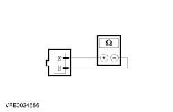
- a) Measure the resistance at the air conditioning clutch relay, between pin 3 and pin 5, component side.
- Check the normally open contact in the switched state:
- a) Use a fused test cable (1 A) to connect pin 1 of the air conditioning clutch relay, component side, to the battery positive terminal.
- b) Use a test cable to connect pin 2 of the air conditioning clutch relay, component side, to the battery negative terminal.
- c) Measure the resistance at the air conditioning clutch relay, between pin 3 and pin 5, component side.
- d) Is a resistance of less than 2 Ohm measured?
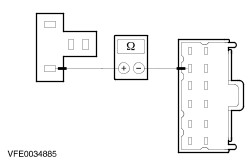
1. If yes, then the air conditioning clutch relay is OK. 2. If no, RENEW the air conditioning clutch relay. A/C relay - Check the normally open contact in the unswitched state:
- a) Measure the resistance at the air conditioning relay, between pin 3 and pin 5, component side.
- Check the normally open contact in the switched state:
- a) Use a fused test cable (1 A) to connect pin 1 of the air conditioning relay, component side, to the battery positive terminal.
- b) Use a test cable to connect pin 2 of the air conditioning relay, component side, to the battery negative terminal.
- c) Measure the resistance at the air conditioning relay, between pin 3 and pin 5, component side.
- d) Is a resistance of less than 2 Ohm measured?
1. If yes, the air conditioning relay is OK. 2. If no, RENEW the air conditioning relay. Testing the refrigerant circuit - vehicles built up to 10/2002 Workshop equipment The following auxiliary equipment is required for testing: - R134a refrigerant center or R134a pressure gauge set
- Stopwatch
Pinpoint test: Refrigerant circuit WARNING:The air conditioning system is filled with refrigerant R134a. Observe "Health and Safety Precautions". For further information
REFER to: Gesundheits- und Sicherheitsvorkehrungen (100-00, Description and Operation).
NOTE:The following pinpoint test only applies to vehicles with compressors without low-pressure circuit control. The following values must be determined: - Low pressure
- High pressure
- Cycle time
Test Preparations Before testing, ensure that the heater control valve, the air flaps and the radiator fan function correctly. WARNING:The manufacturer's instructions must be followed when connecting the R134a refrigerant center or the R134a pressure gauge set. Failure to observe this instruction can lead to injuries. CAUTION:The refrigerant analyzer must be used prior to connecting the R134a refrigerant center or the R134a pressure gauge set, otherwise the refrigerant center may become contaminated. Contaminated refrigerant must be disposed of as hazardous waste. The following steps must be followed carefully to guarantee accurate test results. - Connect the R134a refrigerant center or the R134a pressure gauge set to the refrigerant circuit.
- Start the engine.
- Switch on the air-conditioning system.
- Switch on the air recirculation system.
- Set the blower switch to “maximum”.
- Run the engine for approx. 10 minutes at 1500 rpm.
Check the cycle time and system pressures Allow the engine to run at 1500 rpm during the test. - Set the temperature control to maximum cooling output.
- Measure the cycles (ON and OFF times of the A/C clutch) with a stopwatch and note the results.
- Take readings from the high and low pressure gauges and note the values.
- Compare the obtained cycle times and pressure values with the following specified values and use the Symptom Chart to determine the cause of the fault.
Example: - High pressure too low
- Low pressure normal
- Overall cycle time too short
- “A/C clutch closed” cycle time too short
- “A/C clutch open” cycle time too short
Fault cause: Refrigerant quantity insufficient. Target values The high and low pressure values and the cycle times are dependent upon the ambient temperature. The ambient temperature should be measured at a distance of 1 m from the vehicle. The applicable tolerance range which describes the "normal" range for a measured value, lies between the upper and lower curves. High pressure | Co-ordinate axis | Description | | 1 | High pressure (bar) | | 2 | Ambient temperature (°C) | Low pressure | Co-ordinate axis | Description | | 1 | Low pressure (bar) | | 2 | Ambient temperature (°C) | A/C clutch switched on | Co-ordinate axis | Description | | 1 | A/C clutch switched on (seconds) | | 2 | Ambient temperature (°C) | A/C clutch switched off | Co-ordinate axis | Description | | 1 | A/C clutch switched off (seconds) | | 2 | Ambient temperature (°C) | Total cycle time NOTE:The total cycle time is made up of the “A/C clutch ON time” and the “A/C clutch OFF time”. | Co-ordinate axis | Description | | 1 | Total cycle time (seconds) | | 2 | Ambient temperature (°C) | Symptom Chart: Refrigerant Circuit | High pressure | Low pressure | Total cycle time | “A/C clutch closed” cycle time | “A/C clutch open” cycle time | Fault cause | | too high | too high | too long | continuously switched on | - | Inadequate heat dissipation at the condenser (e.g. cooling fans inoperative, external contamination of or damage to the condenser) | | normal to too high | normal | too long | continuously switched on | - | Air, foreign material or too much refrigerant in the refrigerant circuit | | normal | too high | too long | continuously switched on | - | Fixed orifice tube O-rings leaking/damaged | | normal | normal | too long | too long to continuous | normal to not at all | Foreign bodies (e.g. moisture) or too much refrigerant oil in the refrigerant circuit | | normal | too low | too long | too long | too long | Refrigerant low-pressure switch faulty | | normal to too low | too high | too long | continuously switched on | - | Faulty A/C compressor | | normal to too low | normal to too high | too long | continuously switched on | - | Low pressure line to the A/C compressor blocked | | normal to too low | normal | too short | too short | normal | Evaporator blocked | | normal to too low | normal | too short to normal | too short | normal to too long | Condenser core, fixed orifice tube or high-pressure line blocked | | normal to too low | normal | too short | too short | too short | Refrigerant quantity insufficient | | normal to too low | normal | too short | too short | too long | High-pressure line to the evaporator blocked | | normal to too low | too low | too long | continuously switched on | - | Low pressure line to the A/C compressor blocked or control fault via refrigerant low-pressure switch (fails to switch off) | |