| PINPOINT TEST A : THE HEADLAMPS ON REMINDER CHIME IS INOPERATIVE/DOES NOT OPERATE CORRECTLY |
| TEST CONDITIONS | DETAILS/RESULTS/ACTIONS |
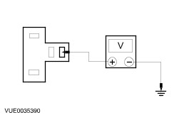
| A1: CHECK CIRCUIT 29S-WA9 (OG/BK) FOR VOLTAGE |
| | 1 Disconnect Lights-ON-Warning Buzzer C147. |
| | 2 Place the headlamp switch in the LOW BEAM position. |
| | 3 Measure the voltage between the lights-ON-warning buzzer C147 pin 5, circuit 29S-WA9 (OG/BK), harness side and ground. |
| | Is the voltage greater than 10 volts? Yes No |
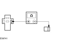
| A2: CHECK CIRCUIT 29S-WA9 (OG/BK) FOR OPEN |
| | 1 Measure the resistance between the lights-ON-warning buzzer C147 pin 5, circuit 29S-WA9 (OG/BK), and the number 6 fuse holder in the CJB. |
| | Is the resistance less than 5 ohms? Yes No REPAIR the circuit. TEST the system for normal operation. |
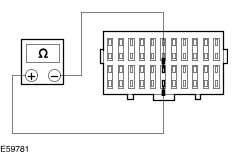
| A3: CHECK CJB FOR OPEN |
| | 1 Disconnect Fuse 6. |
| | 2 Measure the resistance between the electrical connectors for fuse 6 within the CJB. |
| | Is the resistance less than 5 ohms? Yes No INSTALL a new CJB. TEST the system for normal operation. |
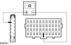
| A4: CHECK CIRCUIT 29S-DB7 (OG/YE) FOR OPEN |
| | 1 Disconnect Headlamp Switch C102A. |
| | 2 Measure the resistance between the headlamp switch C102A pin 7, circuit 29S-DB7 (OG/YE), and the number 6 fuse holder in the CJB. |
| | Is the resistance less than 5 ohms? Yes No REPAIR the circuit. TEST the system for normal operation. |
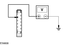
| A5: TEST THE HEADLAMP SWITCH OUTPUT |
| | 1 Measure the voltage between the headlamp switch C102A pin 7, circuit 29S-DB7 (OG/YE), harness side and ground. |
| | Is the voltage greater than 10 volts? Yes No INSTALL a new headlamp switch. TEST the system for normal operation. |
| A6: CHECK THE DRIVER SIDE INTERIOR LAMP SWITCH CIRCUIT FOR OPEN |
| | 1 Disconnect Driver Side Interior Lamp Switch C124 (LHD) or C125 (RHD). |
| | 2 Measure the resistance between: - (LHD) the lights-ON-warning buzzer C147 pin 1, circuit 31S-LC9 (BK/RD) and the driver side interior lamp switch C124 pin 1, harness side.
- (RHD) the lights-ON-warning buzzer C147 pin 1, circuit 31S-LC21 (BK/GN) and the driver side interior lamp switch C125 pin 1, harness side.
|
| | Is the resistance less than 5 ohms? Yes Install a new lights-ON-warning buzzer. TEST the system for normal operation. No REPAIR circuit 31S-LC9 (BK/RD) or circuit 31S-LC9 (BK/GN). TEST the system for normal operation. |