| Diagnosis and Testing Refer to Wiring Diagrams Section 415-01, for schematic and connector information.Refer to Wiring Diagrams Section 415-02, for schematic and connector information.Refer to Wiring Diagrams Section 415-03, for schematic and connector information. Inspection and Verification NOTE:If the code is entered incorrectly 3 times, the system will lock out. The component can only be unlocked by the manufacturer. - Verify the customer concern.
- Visually inspect for obvious signs of mechanical or electrical damage.
Visual Inspection Chart | Mechanical | Electrical | - Cassette player
- Foreign objects contacting speaker(s)
- Trim poorly fitted/resonance
- Antenna mast or base
| - Fuse(s)
- Wiring harness
- Electrical connector(s)
- Speaker(s)
- Audio unit
| - If an obvious cause for an observed or reported concern is found, correct the cause (if possible) before proceeding to the next step.
- If an obvious cause is not found, codes maybe shown in the audio unit display. Check the audio unit display for the following error codes:
- for vehicles with 6000 audio unit refer to the CD Error Codes - vehicles with 6000 Audio Unit
- for vehicles with 6006E audio unit refer to the CD Error Codes - vehicles with Vehicles with 6006E Audio Unit
CD Error Codes Vehicles with 6006E Audio Unit Error Codes | Error Code | Error Description | Error Rectification | | E1 | Communications Error | Install a new audio unit.
REFER to: Audio Unit (415-01 Audio Unit, Removal and Installation).
TEST the system for normal operation. | | E2 | Overtemp Error | The Audio unit is too hot, it will not work until it has cooled down. Check the heater duct(s) are not bleeding hot air on to the audio unit.
REFER to: Audio Unit (415-01 Audio Unit, Removal and Installation).
If the concern persists, INSTALL a new audio unit. TEST the system for normal operation. | | E3 | Mechanical Error | PRESS and HOLD the LOAD and EJECT buttons simutaneously. WAIT until the audio unit has checked through the CDs currently in the unit. TEST the system for normal operation. If the concern persists, DISCONNECT the audio unit power connector. WAIT 20 seconds and then CONNECT the audio unit power connector. WAIT until the audio unit has checked through the CDs currently in the unit. TEST the system for normal operation. If the error code is still displayed, INSTALL a new audio unit.
REFER to: Audio Unit (415-01 Audio Unit, Removal and Installation).
TEST the system for normal operation. | | E4 | Focus Error | CD is upside down or dirty. Clean the CD and try it again, if the error code is still displayed, INSERT a different CD. If the error code is still displayed. INSTALL a new audio unit.
REFER to: Audio Unit (415-01 Audio Unit, Removal and Installation).
TEST the system for normal operation. | | E5 | Overcurrent Error | Install a new audio unit.
REFER to: Audio Unit (415-01 Audio Unit, Removal and Installation).
TEST the system for normal operation. | CD Error Codes - vehicles with 6000 Audio Unit Error Codes | Error Code | Error Description | Error Rectification | | E11 | SPI Bus Failure | CHECK and REPAIR the wiring harness. If the wiring harness is OK, DISCONNECT the audio unit power connector, SWITCH the audio unit ON and OFF four times then CONNECT the audio unit power connector. TEST the system for normal operation. If the error code is still displayed, INSTALL a new audio unit.
REFER to: Audio Unit (415-01 Audio Unit, Removal and Installation).
TEST the system for normal operation. | | E12 | Communications Error | CHECK and REPAIR the wiring harness. If the wiring harness is OK, DISCONNECT the audio unit power connector, SWITCH the audio unit ON and OFF four times then CONNECT the audio unit power connector. TEST the system for normal operation. If the error code is still displayed, INSTALL a new audio unit.
REFER to: Audio Unit (415-01 Audio Unit, Removal and Installation).
TEST the system for normal operation. | | E14 | Overtemp Error | The Audio unit is too hot, unit will not work until it has cooled down. Check the heater duct(s) are not bleeding hot air on to the radio. If the concern persists, INSTALL a new audio unit.
REFER to: Audio Unit (415-01 Audio Unit, Removal and Installation).
TEST the system for normal operation. | | E15 | Mechanical Error | Install a new audio unit.
REFER to: Audio Unit (415-01 Audio Unit, Removal and Installation).
TEST the system for normal operation. | | E16 | CD Eject Failure | Install a new audio unit.
REFER to: Audio Unit (415-01 Audio Unit, Removal and Installation).
TEST the system for normal operation. | Self-Diagnostic Mode - To enter the audio unit Self-Diagnostic Mode, switch the audio unit ON. Within four seconds depress the preset buttons 3 and 6 together.
- Release the preset buttons 3 and 6 and the audio unit will enter the Self-Diagnostic Mode.
- To navigate through the audio unit Self-Diagnostic Mode, depress the preset button 6 (manual cycle).
- To exit the Self-Diagnostic Mode do not press any button on the audio unit for 10 seconds (manual cycle).
Self-Diagnostic Mode | Test | Syntax Displayed | Circuit Tested | Description | Action | | 1. FM waveband check. | FM frequency received. | Antenna signal. | Tests signal from the antenna cable. | If a concern is present, GO to Pinpoint Test B. | | 2. Test speaker circuit right hand front speaker(s). | 4CH RF for four channel system 2CH RF for two channel system. | Right hand front speaker circuit. | Test speaker circuit. | If a concern is present, GO to Pinpoint Test C. | | 3. Test speaker circuit left hand front speaker(s). | 4CH LF for four channel system 2CH LF for two channel system. | Left hand front speaker circuit. | Test speaker circuit. | If a concern is present. GO to Pinpoint Test D. | - If the concern is still evident after the self-diagnostic mode, refer to the Symptom Chart.
Symptom Chart | Symptom | Possible Sources | Action | | The audio unit is inoperative/does not operate correctly | * Circuit(s). * Audio unit. | * | | Poor quality/distorted sound from one or more speakers (not all speakers) | * Trim resonance. | * Make sure the trims around the speakers are secure. | | No sound from all speakers | * Audio unit. | * INSTALL a new audio unit.
REFER to: Audio Unit (415-01 Audio Unit, Removal and Installation).
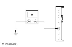
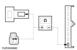
TEST the system for normal operation. | Pinpoint Tests NOTE:Use a digital multimeter for all electrical measurements. | PINPOINT TEST A : THE AUDIO UNIT IS INOPERATIVE/DOES NOT OPERATE CORRECTLY | | TEST CONDITIONS | DETAILS/RESULTS/ACTIONS | | A1: CHECK CIRCUIT 29-MD15 (OG/BK) FOR POWER | | | 1 Disconnect Audio unit C7a. | | | 2 Measure the voltage between the audio unit C7a pin 1, circuit 29-MD15 (OG/BK), harness side and ground. | | | Is the voltage greater than 10 volts? Yes No REPAIR the circuit. TEST the system for normal operation. | | A2: CHECK CIRCUIT 74-MD15 (BU/BK) FOR POWER | | | 1 Ignition switch in position I. | | | 2 Measure the voltage between the audio unit C7a pin 3, circuit 74-MD15 (BU/BK), harness side and ground. | | | Is the voltage greater than 10 volts? Yes No REPAIR the circuit. TEST the system for normal operation. | | A3: CHECK THE AUDIO UNIT GROUND CIRCUIT 91-MD34 (BK/YE) AND 91-MD15 (BK/GN) FOR OPEN | | | 1 Measure the resistance between the audio unit C7a pin 2, circuit 91-MD34 (BK/YE), harness side and ground, and pin 6, circuit 91-MD15 (BK/GN), harness side and ground. | | | Are the resistances less than 1 ohm? Yes INSTALL a new audio unit.
REFER to: Audio Unit (415-01 Audio Unit, Removal and Installation).
TEST the system for normal operation. No REPAIR the circuit(s). TEST the system for normal operation. | | PINPOINT TEST B : POOR RECEPTION | | TEST CONDITIONS | DETAILS/RESULTS/ACTIONS | | B1: CHECK ANTENNA GROUND | | | 1 Ignition switch in position 0. | | | 2 Disconnect Audio unit antenna connector. | | | 3 Measure the resistance between the antenna screen and ground. | | | Is the resistance less than 1 ohm? Yes No CLEAN and TIGHTEN the audio unit case ground and the antenna mast base connection to the body. If concern persists, INSTALL a new antenna cable.
REFER to: Antenna (415-02 Antenna, Removal and Installation).
TEST the system for normal operation.
REFER to: Antenna Cable - Convertible (415-02 Antenna, Removal and Installation).
| | B2: CHECK ANTENNA CABLE FOR OPEN | | | 1 Remove the antenna mast. | | | 2 Measure the resistance between the center pin on the antenna connector and the antenna mast screw thread. | | | Is the resistance less than 1 ohm? Yes No INSTALL a new antenna cable.
REFER to: Antenna Cable - Convertible (415-02 Antenna, Removal and Installation).
TEST the system for normal operation. | | B3: CHECK ANTENNA CABLE FOR SHORT | | | 1 Disconnect Antenna base connector. | | | 2 Measure the resistance between the center pin on the antenna core and the antenna screen. | | | Is the resistance greater than 10,000 ohms (open circuit)? Yes INSTALL a new antenna.
REFER to: Antenna (415-02 Antenna, Removal and Installation).
TEST the system for normal operation. No INSTALL a new antenna cable.
REFER to: Antenna Cable - Convertible (415-02 Antenna, Removal and Installation).
TEST the system for normal operation. | | PINPOINT TEST C : CONCERN WITH THE RH SIDE FRONT SPEAKER CIRCUIT(S) | | TEST CONDITIONS | DETAILS/RESULTS/ACTIONS | | C1: CHECK THE RH SIDE FRONT SPEAKER CIRCUIT 8-MD17 (WH/RD) FOR OPEN | | | 1 Disconnect Audio unit C7b. | | | 2 Disconnect RH side front speaker. - C325 (up to 09/00).
- C327 (09/00 onwards).
| | | | | | 3 Measure the resistance between the audio unit C7b pin 5, circuit 8-MD17 (WH/RD), harness side and RH side front speaker C325 pin 2, circuit 8-MD17 (WH/RD), harness side (up to 09/00) / C327 pin 1, circuit 8-MD17 (WH/RD), harness side (09/00 onwards). | | | Is the resistance less than 1 ohm? Yes No REPAIR the circuit. TEST the system for normal operation. | | C2: CHECK THE RH SIDE FRONT SPEAKER CIRCUIT 10-MD17 (GY/RD) FOR OPEN | | | | | | 1 Measure the resistance between the audio unit C7b pin 6, circuit 10-MD17 (GY/RD), harness side and RH side front speaker C325 pin 2, circuit 10-MD17 (GY/RD), harness side (up to 09/00) / C327 pin 1, circuit 10-MD17 (GY/RD), harness side (09/00 onwards). | | | Is the resistance less than 1 ohm? Yes No REPAIR the circuit. TEST the system for normal operation. | | C3: CHECK THE RH SIDE FRONT SPEAKER CIRCUIT 10-MD17 (GY/RD) | | | 1 Measure the resistance between the audio unit C7b pin 6, circuit 10-MD17 (GY/RD), harness side and ground. | | | Is the resistance greater than 10,000 ohms (open circuit)? Yes INSTALL a new RH side front speaker. TEST the system for normal operation. If the concern persists, INSTALL a new audio unit.
REFER to: Audio Unit (415-01 Audio Unit, Removal and Installation).
No REPAIR the circuit. For additional information, REFER to the wiring diagrams. TEST the system for normal operation. | | PINPOINT TEST D : CONCERN WITH THE LH SIDE FRONT SPEAKER CIRCUIT(S) | | TEST CONDITIONS | DETAILS/RESULTS/ACTIONS | | D1: CHECK THE LH SIDE FRONT DOOR SPEAKER CIRCUIT 8-MD10 (WH/RD) FOR OPEN | | | 1 Disconnect Audio unit C7b. | | | 2 Disconnect LH side front door speaker. - C324 (up to 09/00).
- C326 (09/00 onwards).
| | | | | | 3 Measure the resistance between the audio unit C7b pin 1, circuit 8-MD10 (WH/RD), harness side and LH side front speaker C324, pin 2 circuit 8-MD17 (WH/RD), harness side (up to 09/00) / C326 pin 1, circuit 8-MD17 (WH/RD), harness side (09/00 onwards). | | | Is the resistance less than 1 ohm? Yes No REPAIR the circuit. TEST the system for normal operation. | | D2: CHECK THE LH SIDE FRONT DOOR SPEAKER CIRCUIT 10-MD10 (GY/RD) FOR OPEN | | | | | | 1 Measure the resistance between the audio unit C7b pin 2, circuit 10-MD10 (GY/RD), harness side and LH side front door speaker C324, pin 1 circuit 10-MD10 (GY/RD), harness side (up to 09/00) / C326 pin 2, circuit 10-MD17 (GY/RD), harness side (09/00 onwards). | | | Is the resistance less than 1 ohm? Yes No REPAIR the circuit. TEST the system for normal operation. | | D3: CHECK THE LH SIDE FRONT SPEAKER CIRCUIT 10-MD17 (GY/RD) | | | 1 Measure the resistance between the audio unit C7b pin 2, circuit 10-MD17 (GY/RD), harness side ground. | | | Is the resistance greater than 10,000 ohms (open circuit)? Yes INSTALL a new LH side front speaker. TEST the system for normal operation. If the concern persists, INSTALL a new audio unit.
REFER to: Audio Unit (415-01 Audio Unit, Removal and Installation).
No REPAIR the circuit. For additional information, REFER to the wiring diagrams. TEST the system for normal operation. | |