| PINPOINT TEST A : THE ALARM SYSTEM DOES NOT OPERATE CORRECTLY |
| TEST CONDITIONS | DETAILS/RESULTS/ACTIONS |
| A1: CARRY OUT THE ALARM SYSTEM SELF-TEST |
| | 1 Carry out the alarm system self-test. REFER to the Alarm System Self-Test in this procedure. |
| | Do all of the tested inputs from the alarm system self-test respond correctly? Yes No If the alarm system is completely inoperative. GO to A7. If the anti-theft alarm horn with integral battery does not sound when the hood is opened. GO to A9. If the anti-theft alarm horn with integral battery does not sound when the driver door is opened. GO to A12. If the anti-theft alarm horn with integral battery does not sound when the passenger door is opened. GO to A13. If the anti-theft alarm horn with integral battery does not sound when the liftgate is opened. (Sportka only) GO to A15. If the anti-theft alarm horn with integral battery does not sound when the luggage compartment lid is opened. (Streetka only) GO to A19. If the anti-theft alarm horn with integral battery does not sound when the convertible top stowage compartment is opened. (Streetka only) GO to A23. If the anti-theft alarm horn with integral battery does not sound when the microwave sensor is tested. GO to A26. If the anti-theft alarm horn with integral battery does not sound when the ignition key is turned to position II. GO to A28. |
| A2: CHECK THE OPERATION OF THE ALARM SYSTEM |
| | 1 Arm and disarm the alarm system using the remote transmitter. |
| | Does the alarm system operate correctly? Yes Lock the vehicle using the remote transmitter. Test the system for normal operation. No If the alarm system does not arm. GO to A3. If the alarm system does not disarm. GO to A5. |
| A3: CHECK THE ALARM SYSTEM ARMING POSITIVE SIGNAL |
| | 1 Disconnect Alarm Module C530. |
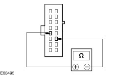
| | 2 Measure the resistance between the alarm module C530 pin 12, circuit 33-AA3B (YE/RD), harness side and the alarm module C530 pin 3, circuit 33-AA3B (YE/RD), harness side. |
| | Is the resistance less than 5 ohms? Yes No REPAIR circuit 33-AA3B. TEST the system for normal operation. |
| A4: CHECK THE ALARM SYSTEM ARMING NEGATIVE SIGNAL |
| | 1 Disconnect Door Locking Module C1257. |
| | 2 Measure the resistance between the alarm module C530 pin 11, circuit 31S-AA8B (BK/OG), harness side and the door locking module C1257 pin 6, circuit 31S-AA8C (BK/OG), harness side. |
| | Is the resistance less than 5 ohms? Yes INSTALL a new alarm module. TEST the system for normal operation. No REPAIR circuit 31S-AA8B (BK/OG) or 31S-AA8C (BK/OG) as necessary. TEST the system for normal operation. |
| A5: CHECK THE ALARM SYSTEM DISARMING NEGATIVE UNLOCKING SIGNAL |
| | 1 Disconnect Alarm Module C530. |
| | 2 Disconnect Door Locking Module C1256. |
| | 3 Measure the resistance between the alarm module C530 pin 3, circuit 33-AA3A (YE/RD), harness side and the door locking module C1256 pin 8, circuit 33-AA3 (YE/RD), harness side. |
| | Is the resistance less than 5 ohms? Yes No REPAIR circuit 33-AA3A (YE/RD) or circuit 33-AA3 (YE/RD) as necessary. TEST the system for normal operation. |
| A6: CHECK THE ALARM SYSTEM DISARMING NEGATIVE INTERIOR LIGHT SIGNAL |
| | 1 Disconnect Entry Illumination Diode C531. |
| | 2 Measure the resistance between the alarm module C530 pin 4, circuit 31S-AA36A (BK/YE), harness side and the entry illumination diode C531, circuit 31S-AA36B (BK/YE), harness side. |
| | Is the resistance less than 5 ohms? Yes INSTALL a new alarm module. TEST the system for normal operation. No REPAIR circuit 31S-AA36A (BK/YE) or circuit 31S-AA36B (BK/YE) as necessary. TEST the system for normal operation. |
| A7: CHECK THE ALARM MODULE FOR VOLTAGE |
| | 1 Disconnect Alarm Module C530. |
| | 2 Measure the voltage between the alarm module C530 pin 10, circuit 30-GL13 (RD) (Streetka) or circuit 29-GL13 (OG/YE) (Sportka), harness side and ground. |
| | Is the voltage greater than 10 volts? Yes No REPAIR circuit 30-GL13 (RD) or circuit 29-GL13 (OG/YE) as necessary. TEST the system for normal operation. |
| A8: CHECK THE ALARM MODULE GROUND CIRCUIT FOR OPEN |
| | 1 Measure the resistance between the alarm module C530 pin 2, circuit 31-GL13 (BK), harness side and ground. |
| | Is the resistance less than 5 ohms? Yes INSTALL a new alarm module. TEST the system for normal operation. No REPAIR circuit 31-GL13 (BK). TEST the system for normal operation. |
| A9: CHECK THE HOOD CIRCUIT FOR OPEN |
| | 1 Disconnect Alarm Module C530. |
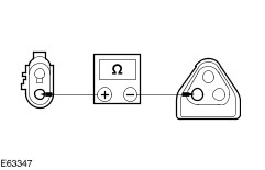
| | 2 Disconnect Hood Switch C604. |
| | 3 Measure the resistance between the alarm module C530 pin 13, circuit 31S-GL27A (BK/OG), harness side and the hood switch C604 pin 1, circuit 31S-GL51 (BK/RD), harness side. |
| | Is the resistance less than 5 ohms? Yes No REPAIR circuit 31S-GL27A (BK/OG) or circuit 31S-GL51 (BK/RD) as necessary. TEST the system for normal operation. |
| A10: CHECK THE HOOD SWITCH GROUND CIRCUIT |
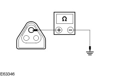
| | 1 Measure the resistance between the hood switch C604 pin 2, circuit 31-GL51 (BK), harness side and ground. |
| | Is the resistance less than 5 ohms? Yes No REPAIR circuit 31-GL51 (BK). TEST the system for normal operation. |
| A11: CHECK THE OPERATION OF THE HOOD SWITCH CIRCUIT |
| | 1 Connect Hood Switch C604. |
| | 2 Measure the resistance between the alarm module C530 pin 13, circuit 31S-GL27A (BK/OG), harness side and ground, while operating the hood switch. |
| | Is the resistance less than 5 ohms with the switch released and greater than 10,000 ohms with the switch pressed? Yes INSTALL a new hood switch. TEST the system for normal operation. No INSTALL a new alarm module. TEST the system for normal operation. |
| A12: CHECK THE CIRCUIT 31S-LC29 (BK/RD) FOR OPEN |
| | 1 Disconnect Lights-ON-Warning Module C59. |
| | 2 Disconnect Driver Door Switch C26. |
| | 3 Measure the resistance between the lights-ON-warning module C59 pin 1, circuit 31S-LC29 (BK/RD), harness side and the driver door switch C26, circuit 31S-LC29 (BK/RD), harness side. |
| | Is the resistance less than 5 ohms? Yes REFER to: Warning Devices - Vehicles Built Up To: 01/2005 (413-09 Warning Devices, Diagnosis and Testing). No REPAIR circuit 31S-LC29 (BK/RD). TEST the system for normal operation. |
| A13: CHECK THE CIRCUIT 31S-LC30 (BK/GN) FOR OPEN |
| | 1 Disconnect Lights-ON-Warning Module C59. |
| | 2 Disconnect Passenger Door Switch C55. |
| | 3 Measure the resistance between the lights-ON-warning module C59 pin 2, circuit 31S-LC30 (BK/GN), harness side and the passenger door switch C55, circuit 31S-LC30 (BK/GN), harness side. |
| | Is the resistance less than 5 ohms? Yes No REPAIR circuit 31S-LC30 (BK/GN). TEST the system for normal operation. |
| A14: CHECK THE CIRCUIT 31S-GM12 (BK/GN) FOR OPEN |
| | 1 Disconnect Alarm Module C530. |
| | 2 Measure the resistance between the alarm module C530 pin 6, circuit 31S-GM12 (BK/GN), harness side and the passenger door switch C55, circuit 31S-GM12 (BK/GN), harness side. |
| | Is the resistance less than 5 ohms? Yes REFER to: Warning Devices - Vehicles Built Up To: 01/2005 (413-09 Warning Devices, Diagnosis and Testing). No REPAIR circuit 31S-GM12 (BK/GN). TEST the system for normal operation. |
| A15: CHECK THE LIFTGATE SWITCH CIRCUIT FOR OPEN (SPORTKA ONLY) |
| | 1 Disconnect Alarm Module C530. |
| | 2 Disconnect Alarm System Blocking Diode C540. |
| | 3 Measure the resistance between the alarm module C530 pin 13, circuit 31S-GL27A (BK/OG), harness side and the alarm system blocking diode C540 pin 1, circuit 31S-GL27B (BK/OG), harness side. |
| | Is the resistance less than 5 ohms? Yes No REPAIR circuit 31S-GL27A (BK/OG) or circuit 31S-GL27B (BK/OG) as necessary. TEST the system for normal operation. |
| A16: CHECK THE CIRCUITS 31S-GL35 (BK/GN) AND 31S-LB26 (BK/OG) FOR OPEN (SPORTKA ONLY) |
| | 1 Disconnect Liftgate Switch C1284. |
| | 2 Measure the resistance between the alarm system blocking diode C540 pin 2, circuit 31S-GL35 (BK/GN), harness side and the liftgate switch C1284 pin 3, circuit 31S-LB26 (BK/OG), harness side. |
| | Is the resistance less than 5 ohms? Yes No REPAIR circuit 31S-GL35 (BK/GN) or circuit 31S-GL26 (BK/OG) as necessary. TEST the system for normal operation. |
| A17: CHECK THE LIFTGATE SWITCH GROUND CIRCUIT FOR OPEN |
| | 1 Measure the resistance between the liftgate switch C1284 pin 2, circuit 31-LB26 (BK), harness side and ground. |
| | Is the resistance less than 5 ohms? Yes No REPAIR circuit 31-LB26 (BK). TEST the system for normal operation. |
| A18: CHECK THE OPERATION OF THE LIFTGATE SWITCH CIRCUIT |
| | 1 Connect Liftgate Switch C1284. |
| | 2 Measure the resistance between the alarm module C530 pin 13, circuit 31S-GL27A (BK/OG), harness side and ground, while operating the liftgate switch. |
| | Is the resistance less than 5 ohms with the switch released and greater than 10,000 ohms with the switch pressed? Yes INSTALL a new liftgate switch. TEST the system for normal operation. No INSTALL a new alarm system blocking diode. TEST the system for normal operation. If the concern persists, INSTALL a new alarm module. TEST the system for normal operation. |
| A19: CHECK THE LUGGAGE COMPARTMENT LID SWITCH CIRCUIT FOR OPEN (STREETKA ONLY) |
| | 1 Disconnect Alarm Module C530. |
| | 2 Disconnect Alarm System Blocking Diode C540. |
| | 3 Measure the resistance between the alarm module C530 pin 13, circuit 31S-GL27A (BK/OG), harness side and the alarm system blocking diode C540 pin 1, circuit 31S-GL27B (BK/OG), harness side. |
| | Is the resistance less than 5 ohms? Yes No REPAIR circuit 31S-GL27A (BK/OG) or circuit 31S-GL27B (BK/OG) as necessary. TEST the system for normal operation. |
| A20: CHECK THE CIRCUITS 31S-GL35 (BK/GN) AND 31S-LB26 (BK/OG) FOR OPEN (STREETKA ONLY) |
| | 1 Disconnect Luggage Compartment Lid Switch C537. |
| | 2 Measure the resistance between the alarm system blocking diode C540 pin 2, circuit 31S-GL35 (BK/GN), harness side and the luggage compartment lid switch C537 pin 2, circuit 31S-LB26 (BK/OG), harness side. |
| | Is the resistance less than 5 ohms? Yes No REPAIR circuit 31S-GL35 (BK/GN) or circuit 31S-LB26 (BK/OG) as necessary. TEST the system for normal operation. |
| A21: CHECK THE LUGGAGE COMPARTMENT LID SWITCH GROUND CIRCUIT FOR OPEN (STREETKA ONLY) |
| | 1 Measure the resistance between the luggage compartment lid switch C537 pin 3, circuit 31-AA24 (BK), harness side and ground. |
| | Is the resistance less than 5 ohms? Yes No REPAIR circuit 31-AA24 (BK). TEST the system for normal operation. |
| A22: CHECK THE OPERATION OF THE LUGGAGE COMPARTMENT LID SWITCH CIRCUIT (STREETKA ONLY) |
| | 1 Connect Luggage Compartment Lid Switch C537. |
| | 2 Measure the resistance between the alarm module C530 pin 13, circuit 31S-GL27A (BK/OG), harness side and ground, while operating the luggage compartment lid switch. |
| | Is the resistance less than 5 ohms with the switch released and greater than 10,000 ohms with the switch pressed? Yes INSTALL a new luggage compartment lid switch. TEST the system for normal operation. No INSTALL a new alarm system blocking diode. TEST the system for normal operation. If the concern persists, INSTALL a new alarm module. TEST the system for normal operation. |
| A23: CHECK THE CONVERTIBLE TOP STORAGE COMPARTMENT LID SWITCH CIRCUIT (STREETKA ONLY) |
| | 1 Disconnect Alarm Module C530. |
| | 2 Disconnect Convertible Top Storage Compartment Lid Switch C536. |
| | 3 Measure the resistance between the alarm module C530 pin 13, circuit 31S-GL27A (BK/OG), harness side and the convertible top storage compartment lid switch C536 pin 1, circuit 31S-GL27 (BK/OG), harness side. |
| | Is the resistance less than 5 ohms? Yes No REPAIR circuit 31S-GL27A (BK/OG) or circuit 31S-GL27 (BK/OG) as necessary. TEST the system for normal operation. |
| A24: CHECK THE CONVERTIBLE TOP STORAGE COMPARTMENT LID SWITCH GROUND CIRCUIT FOR OPEN (STREETKA ONLY) |
| | 1 Measure the resistance between the convertible top storage compartment lid switch C536 pin 2, circuit 31-GL27 (BK), harness side and ground. |
| | Is the resistance less than 5 ohms? Yes No REPAIR circuit 31-GL27 (BK). TEST the system for normal operation. |
| A25: CHECK THE OPERATION OF THE CONVERTIBLE TOP STORAGE COMPARTMENT LID SWITCH CIRCUIT (STREETKA ONLY) |
| | 1 Connect Convertible Top Storage Compartment Lid Switch C536. |
| | 2 Measure the resistance between the alarm module C530 pin 13, circuit 31S-GL27A (BK/OG), harness side and ground, while operating the convertible top storage compartment lid switch. |
| | Is the resistance less than 5 ohms with the switch released and greater than 10,000 ohms with the switch pressed? Yes INSTALL a new convertible top storage compartment lid switch. TEST the system for normal operation. No INSTALL a new alarm module. TEST the system for normal operation. |
| A26: CHECK THE MICROWAVE SENSOR CIRCUITS FOR OPEN |
| | 1 Disconnect Alarm Module C530. |
| | 2 Disconnect Microwave Sensor C542. |
| | 3 Measure the resistance between: - the alarm module C530 pin 7, circuit 7-GL10 (YE), harness side and the microwave sensor C542 pin 1, circuit 7-GL10 (YE), harness side
- the alarm module C530 pin 14, circuit 10-GL10 (GY), harness side and the microwave sensor C542 pin 2, circuit 10-GL10 (GY), harness side
|
| | Is the resistance less than 5 ohms? Yes No REPAIR circuit 7-GL10 (YE) or circuit 10-GL10 (GY) as necessary. TEST the system for normal operation. |
| A27: CHECK THE MICROWAVE SENSOR GROUND CIRCUITS |
| | 1 Measure the resistance between: - the microwave sensor C542 pin 3, circuit 91-GL10 (BK/YE), harness side and ground
- the microwave sensor C542 pin 4, circuit 8-XL1 (WH/RD), harness side and ground
|
| | Is the resistance less than 5 ohms? Yes INSTALL a new microwave sensor. TEST the system for normal operation. If the concern persists, INSTALL a new alarm module. TEST the system for normal operation. No REPAIR circuit 91-GL10 (BKYE) or circuit 8-XL1 (WH/RD) as necessary. TEST the system for normal operation. |
| A28: CHECK THE IGNITION CIRCUIT 14-GL13 (VT/YE) |
| | 1 Disconnect Alarm Module C530. |
| | 2 Measure the voltage between the alarm module C530, pin 5, circuit 14-GL13 (VT/YE), harness side and ground. |
| | Is the voltage greater than 10 volts? Yes INSTALL a new alarm module. TEST the system for normal operation. No REPAIR the circuit 14-GL13 (VT/YE). TEST the system for normal operation. |