| Diagnosis and Testing Refer to Wiring Diagrams Section 501-09, for schematic and connector information. Inspection and Verification - Verify the customer concern.
- Visually inspect for obvious signs of mechanical and electrical damage.
Visual Inspection Chart | Mechanical | Electrical | | Exterior mirror(s) | Fuse(s) | | | Relay | | | Electrical connector(s) | | | Switch | - If an obvious cause for an observed or reported concern is found, correct the cause (if possible) before proceeding to the next step.
- If the cause is not visually evident, verify the symptom and refer to the Symptom Chart.
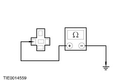
Symptom Chart Symptom Chart | Symptom | Possible Sources | Action | | The mirrors are inoperative | * Exterior mirror control switch. | * CARRY OUT the Exterior Mirror Control Switch Component Test. REFER to the Wiring Diagrams. | | * Circuit(s). | * | | A single mirror is inoperative | * Exterior mirror control switch. | * CARRY OUT the Exterior Mirror Control Switch Component Test. REFER to the Wiring Diagrams. | | * Exterior mirror motor(s). * Circuit(s). | * | | A single mirror does not function with switch logic | * Exterior mirror control switch. | * CARRY OUT the Exterior Mirror Control Switch Component Test. REFER to the Wiring Diagrams. | | * Exterior mirror motor(s). * Circuit(s). | * | | The heated exterior mirror is inoperative | * Heated liftgate window glass control switch. | * CARRY OUT the Heated Liftgate Window Glass Control Switch Component Test. REFER to the Wiring Diagrams. | | * Heated liftgate window glass relay. * Heated mirror glass(es). * Circuit(s). | * Vehicles with 1.3L Endura-E (HCS) engine - GO to Pinpoint Test D. * Vehicles with 1.3/1.6L Duratec-8V (Rocam) engine - GO to Pinpoint Test E. * Convertible - GO to Pinpoint Test F. | Pinpoint Test | PINPOINT TEST A : THE EXTERIOR MIRRORS ARE INOPERATIVE | NOTE:Use a digital multimeter for all electrical measurements. | | TEST CONDITIONS | DETAILS/RESULTS/ACTIONS | | A1: CHECK THE VOLTAGE TO THE EXTERIOR MIRROR CONTROL SWITCH | | | 1 Disconnect Exterior Mirror Control Switch C149. | | | 2 Measure the voltage between the exterior mirror control switch C149 pin 6, circuit 29-AD12 (OG/YE), harness side and ground. | | | Is the voltage greater than 10 volts? Yes No REPAIR circuit 29-AD12 (OG/YE). TEST the system for normal operation. | | A2: CHECK FOR CONTINUITY BETWEEN THE EXTERIOR MIRROR CONTROL SWICH AND GROUND | | | 1 Measure the resistance between the exterior mirror control switch C149 pin 4, circuit 31-AD12 (BK), harness side and ground. | | | Is the resistance less than 5 ohms? Yes No REPAIR circuit 31-AD12 (BK). TEST the system for normal operation. | | A3: CHECK CIRCUIT 9-AD1 (BN/RD) FOR CONTINUITY | | | 1 Disconnect Driver Door A - pillar C1006 (LHD) or C1005 (RHD). | | | 2 Measure the resistance between the: Left-hand drive vehicles - Exterior mirror control switch C149 pin 3, circuit 9-AD1 (BN/RD), harness side, and the driver side door A-pillar C1006 pin 3, circuit 9-AD17 (BN/GN), harness side.
| | | Is the resistance less than 5 ohms? Yes VERIFY the customer concern. No REPAIR circuit 9-AD1 (BN/RD). TEST the system for normal operation. | | PINPOINT TEST B : A SINGLE EXTERIOR MIRROR IS INOPERATIVE | NOTE:Use a digital multimeter for all electrical measurements. | | TEST CONDITIONS | DETAILS/RESULTS/ACTIONS | | B1: CHECK THE INOPERATIVE EXTERIOR MIRROR MOTOR CIRCUIT FOR CONTINUITY | | | 1 Disconnect Exterior Mirror Control Switch C149. | | | 2 Measure the resistance between the: | | | Is the resistance less than 50 ohms? Yes VERIFY the customer concern. No Driver side INSTALL a new exterior mirror.
REFER to: Exterior Mirror (501-09 Rear View Mirrors, Removal and Installation).
| | B2: CHECK FOR CONTINUITY FOR CONTINUITY BETWEEN THE EXTERIOR MIRROR CONTROL SWICH AND THE PASSENGER SIDE EXTERIOR MIRROR | | | 1 Disconnect Passenger Side Exterior Mirror C490. | | | 2 Measure the resistance between the exterior mirror control switch C149 pin 3, circuit 9-AD1 (BN/RD), harness side and the passenger side exterior mirror C490 pin 6, circuit 9-AD17 (BN/GN), harness side. | | | Is the resistance less than 5 ohms? Yes INSTALL a new passenger side exterior mirror.
REFER to: Exterior Mirror (501-09 Rear View Mirrors, Removal and Installation).
TEST the system for normal operation. No REPAIR circuit 9-AD17 (BN/GN). TEST the system for normal operation. | | PINPOINT TEST C : A SINGLE EXTERIOR MIRROR DOES NOT FUNCTION WITH SWITCH LOGIC | NOTE:Use a digital multimeter for all electrical measurements. | | TEST CONDITIONS | DETAILS/RESULTS/ACTIONS | | C1: CHECK THE EXTERIOR MIRROR FUNCTIONS WITH SWITCH LOGIC | | | 1 Operate the exterior mirror control switch. | | | Does the exterior mirror function with switch logic? Yes VERIFY the customer concern. No Driver side exterior mirror up/down function inoperative GO to C2. Driver side exterior mirror left/right function is inoperative GO to C3. Passenger side exterior mirror up/down function is inoperative GO to C4. Passenger side exterior mirror left/right function is inoperative. GO to C6. | | C2: CHECK THE DRIVER SIDE EXTERIOR MIRROR UP/DOWN CIRCUIT | | | 1 Disconnect Exterior Mirror Control Switch C149. | | | 2 Measure the resistance between: Left-hand drive vehicles - Exterior mirror control switch C149 pin 3, circuit 9-AD1 (BN/RD), harness side and the exterior mirror control switch C149 pin 1, circuit 10-AD8 (GY/VT), harness side.
| | | Is the resistance less than 50 ohms? Yes VERIFY the customer concern. No INSTALL a new exterior mirror.
REFER to: Exterior Mirror (501-09 Rear View Mirrors, Removal and Installation).
TEST the system for normal operation. | | C3: CHECK THE DRIVER SIDE EXTERIOR MIRROR LEFT/RIGHT CIRCUIT | | | 1 Disconnect Exterior Mirror Control Switch C149. | | | 2 Measure the resistance between: Left-hand drive vehicles - Exterior mirror control switch C149 pin 3, circuit 9-AD1 (BN/RD), harness side and the exterior mirror control switch C149 pin 7, circuit 8-AD7 (WH/RD), harness side.
| | | Is the resistance less than 50 ohms? Yes VERIFY the customer concern. No INSTALL a new exterior mirror.
REFER to: Exterior Mirror (501-09 Rear View Mirrors, Removal and Installation).
TEST the system for normal operation. | | C4: CHECK THE PASSENGER SIDE EXTERIOR MIRROR UP/DOWN CIRCUIT | | | 1 Disconnect Exterior Mirror Control Switch C149. | | | 2 Measure the resistance between: Left-hand drive vehicles - Exterior mirror control switch C149 pin 3, circuit 9-AD1 (BN/RD), harness side and the exterior mirror control switch C149 pin 2, circuit 10-AD11 (GY/WH), harness side.
| | | Is the resistance less than 50 ohms? Yes VERIFY the customer concern. No | | C5: CHECK FOR CONTINUITY BETWEEN THE EXTERIOR MIRROR CONTROL SWITCH AND THE PASSENGER SIDE EXTERIOR MIRROR UP/DOWN MOTOR | | | 1 Disconnect Passenger Side Exterior Mirror C490. | | | 2 Measure the resistance between: Left-hand drive vehicles - Exterior mirror control switch C149 pin 2, circuit 10-AD11 (GY/WH), harness side, and the passenger side exterior mirror C490 pin 2, circuit 10-AD11 (GY/WH), harness side.
| | | Is the resistance less than 5 ohms? Yes INSTALL a new passenger side exterior mirror.
REFER to: Exterior Mirror (501-09 Rear View Mirrors, Removal and Installation).
TEST the system for normal operation. No REPAIR circuit 10-AD11 (GY/WH). TEST the system for normal operation. | | C6: CHECK THE PASSENGER SIDE EXTERIOR MIRROR LEFT/RIGHT CIRCUIT | | | 1 Disconnect Exterior Mirror Control Switch C149. | | | 2 Measure the resistance between: Left-hand drive vehicles - Exterior mirror control switch C149 pin 2, circuit 10-AD11 (GY/WH), harness side, and the passenger side exterior mirror C490 pin 2, circuit 10-AD11 (GY/WH), harness side.
| | | Is the resistance less than 50 ohms? Yes VERIFY the customer concern. No | | C7: CHECK FOR CONTINUITY BETWEEN THE EXTERIOR MIRROR CONTROL SWITCH AND THE PASSENGER SIDE EXTERIOR MIRROR LEFT/RIGHT MOTOR | | | 1 Disconnect Passenger Exterior Mirror C311. | | | 2 Measure the resistance between: Left-hand drive vehicles - Exterior mirror control switch C149 pin 5, circuit 8-AD10 (WH/BK), harness side, and the passenger side exterior mirror C490 pin 3, circuit 8-AD10 (WH/BK), harness side.
| | | Is the resistance less than 5 ohms? Yes INSTALL a new passenger side exterior mirror.
REFER to: Exterior Mirror (501-09 Rear View Mirrors, Removal and Installation).
TEST the system for normal operation. No REPAIR circuit 8-AD10 (WH/BK). TEST the system for normal operation. | | PINPOINT TEST D : THE HEATED EXTERIOR MIRROR IS INOPERATIVE – VEHICLES WITH 1.3L ENDURA-E (HCS) ENGINE | NOTE:Use a digital multimeter for all electrical measurements. | | TEST CONDITIONS | DETAILS/RESULTS/ACTIONS | | D1: CHECK THE OPERATION OF THE HEATED LIFTGATE WINDOW GLASS RELAY | | | 1 Ignition switch in position II. | | | 2 Operate the heated liftgate window glass control switch. | | | Does the heated liftgate window glass relay operate? Yes No | | D2: CHECK FOR VOLTAGE TO THE INOPERATIVE HEATED EXTERIOR MIRROR – VEHICLES BUILT UP TO 10/2002 | | | 1 Ignition switch in position 0. | | | 2 Disconnect Driver Side Heated Exterior Mirror C148a or Passenger Side Heated Exterior Mirror C147a. | | | 3 Ignition switch in position II. | | | 4 Operate the heated liftgate window glass control switch. | | | 5 Measure the voltage between the: - Driver side heated exterior mirror C148a pin 1, circuit 14S-HB35 (VT/BK), harness side and ground.
- Passenger side heated exterior mirror C147a pin 1, circuit 14S-HB36 (VT/OG), harness side and ground.
| | | Is the voltage greater than 10 volts? Yes No | | D3: CHECK FOR CONTINUITY BETWEEN THE INOPERATIVE HEATED EXTERIOR MIRROR AND GROUND – VEHICLES BUILT UP TO 10/2002 | | | 1 Ignition switch in position 0. | | | 2 Disconnect Driver Side Heated Exterior Mirror C148b or Passenger Side Heated Exterior Mirror C147b. | | | 3 Measure the resistance between the: - Driver side heated exterior mirror C148b pin 1, circuit 31-HB35 (BK), harness side and ground.
- Passenger side heated exterior mirror C147b pin 1, circuit 31-HB36 (BK), harness side and ground.
| | | Is the resistance less than 5 ohms? Yes INSTALL a new heated exterior mirror glass. TEST the system for normal operation. No REPAIR circuit 31-HB35 (BK) or circuit 31-HB36 (BK). TEST the system for normal operation. | | D4: CHECK FOR VOLTAGE TO THE INOPERATIVE HEATED EXTERIOR MIRROR – VEHICLES BUILT FROM 10/2002 | | | 1 Ignition switch in position 0. | | | 2 Disconnect Driver Side Heated Exterior Mirror C485 or Passenger Side Heated Exterior Mirror C490. | | | 3 Ignition switch in position II. | | | 4 Operate the heated liftgate window glass control switch. | | | 5 Measure the voltage between the: - Driver side heated exterior mirror C485 pin 5, circuit 14S-HB35 (VT/BK), harness side and ground.
- Passenger side heated exterior mirror C490 pin 5, circuit 14S-HB36 (VT/OG), harness side and ground.
| | | Is the voltage greater than 10 volts? Yes No | | D5: CHECK FOR CONTINUITY BETWEEN THE INOPERATIVE HEATED EXTERIOR MIRROR AND GROUND – VEHICLES BUILT FROM 10/2002 | | | 1 Measure the resistance between the: - Driver side heated exterior mirror C485 pin 4, circuit 31-DA2 (BK), harness side and ground.
- Passenger side heated exterior mirror C490 pin 4, circuit 31-HB36 (BK), harness side and ground.
| | | Is the resistance less than 5 ohms? Yes INSTALL a new heated exterior mirror glass. TEST the system for normal operation. No REPAIR circuit 31-DA2 (BK) or circuit 31-HB36 (BK). TEST the system for normal operation. | | D6: CHECK FOR CONTINUITY BETWEEN THE HEATED LIFTGATE WINDOW GLASS RELAY AND GROUND | | | 1 Ignition switch in position 0. | | | 2 Disconnect Heated Liftgate Window Glass Relay C48. | | | 3 Measure the resistance between the heated liftgate window glass relay C48 pin 1, circuit 31-DB20 (BK), harness side and ground. | | | Is the resistance less than 5 ohms? Yes No REPAIR circuit 31-DB20 (BK). TEST the system for normal operation. | | D7: CHECK FOR VOLTAGE TO THE HEATED LIFTGATE WINDOW GLASS RELAY | | | 1 Ignition switch in position II. | | | 2 Operate the heated liftgate window glass control switch. | | | 3 Measure the voltage between the heated liftgate window glass relay C48 pin 2, circuit 14S-HB20 (VT/BK), harness side and ground. | | | Is the voltage greater than 10 volts? Yes INSTALL a new heated liftgate window glass relay. TEST the system for normal operation. No | | D8: CHECK FOR BATTERY VOLTAGE TO THE HEATED LIFTGATE WINDOW GLASS RELAY – VEHICLES BUILT UP TO 10/2002 | | | 1 Ignition switch in position 0. | | | 2 Disconnect Heated Liftgate Window Glass Relay C48. | | | 3 Measure the voltage between the heated liftgate window glass relay C48 pin 3, circuit 29-HB21 (OG/GN), harness side and ground. | | | Is the voltage greater than 10 volts? Yes No REPAIR circuit 29-HB21 (OG/GN). TEST the system for normal operation. | | D9: CHECK FOR CONTINUITY BETWEEN THE HEATED LIFTGATE WINDOW GLASS RELAY AND THE HEATED EXTERIOR MIRROR – VEHICLES BUILT UP TO 10/2002 | | | 1 Ignition switch in position 0. | | | 2 Measure the resistance between the: - Heated liftgate window glass relay C48 pin 5, circuit 14S-HB16 (VT/OG), harness side and the driver side heated exterior mirror C148a pin 1, circuit 14S-HB35 (VT/BK), harness side.
- Heated liftgate window glass relay C48 pin 5, circuit 14S-HB16 (VT/OG), harness side and the passenger side heated exterior mirror C147a pin 1, circuit 14S-HB36 (VT/BK), harness side.
| | | Is the resistance less than 5 ohms? Yes INSTALL a new heated liftgate window glass relay. TEST the system for normal operation. No REPAIR circuit 14S-HB16 (VT/OG) or circuit 14S-HB35 (VT/BK) or circuit 14S-HB35 (VT/BK). TEST the system for normal operation. | | D10: CHECK FOR BATTERY VOLTAGE TO THE HEATED LIFTGATE WINDOW GLASS RELAY – VEHICLES BUILT FROM 10/2002 | | | 1 Ignition switch in position 0. | | | 2 Disconnect Heated Liftgate Window Glass Relay C48. | | | 3 Measure the voltage between the heated liftgate window glass relay C48 pin 3, circuit 29-HB21 (OG/GN), harness side and ground. | | | Is the voltage greater than 10 volts? Yes No REPAIR circuit 29-HB21 (OG/GN). TEST the system for normal operation. | | D11: CHECK FOR CONTINUITY BETWEEN THE HEATED LIFTGATE WINDOW GLASS RELAY AND THE HEATED EXTERIOR MIRROR – VEHICLES BUILT FROM 10/2002 | | | 1 Ignition switch in position 0. | | | 2 Measure the resistance between the: - Heated liftgate window glass relay C48 pin 5, circuit 14S-HB16 (VT/OG), harness side and the driver side heated exterior mirror C485 pin 5, circuit 14S-HB35 (VT/BK), harness side.
- Heated liftgate window glass relay C48 pin 5, circuit 14S-HB16 (VT/OG), harness side and the passenger side heated exterior mirror C490 pin 5, circuit 14S-HB36 (VT/BK), harness side.
| | | Is the resistance less than 5 ohms? Yes INSTALL a new heated liftgate window glass relay. TEST the system for normal operation. No REPAIR circuit 14S-HB16 (VT/OG) or circuit 14S-HB35 (VT/BK) or circuit 14S-HB35 (VT/BK). TEST the system for normal operation. | | D12: CHECK OPERATION OF THE HEATED LIFTGATE WINDOW GLASS SWITCH CIRCUIT | | | 1 Operate the heated liftgate window glass control switch. | | | Does the heated liftgate window glass switch LED function correctly? Yes No | | D13: CHECK FOR CONTINUITY BETWEEN THE CLIMATE CONTROL ASSEMBLY AND THE HEATED LIFTGATE WINDOW GLASS RELAY | | | 1 Ignition switch in position 0. | | | 2 Disconnect Climate Control Assembly C41. | | | 3 Measure the resistance between the climate control assembly C41 pin 12, circuit 14S-HB20 (VT/BK), harness side and the heated liftgate window glass relay C48 pin 2, circuit 14S-HB20 (VT/BK), harness side. | | | Is the resistance less than 5 ohms? Yes No REPAIR circuit 14S-HB20 (VT/BK). TEST the system for normal operation. | | D14: CHECK FOR BATTERY VOLTAGE TO THE CLIMATE CONTROL ASSEMBLY | | | 1 Ignition switch in position II. | | | 2 Measure the voltage between the climate control assembly C41 pin 8, circuit 14-CA83 (VT/OG), harness side and ground. | | | Is the voltage greater than 10 volts? Yes INSTALL a new climate control assembly.
REFER to: Climate Control Assembly (412-04 Control Components, Removal and Installation).
TEST the system for normal operation. No REPAIR circuit 14-CA83 (VT/OG). TEST the system for normal operation. | | D15: CHECK FOR CONTINUITY BETWEEN THE CLIMATE CONTROL ASSEMBLY AND GROUND | | | 1 Ignition switch in position 0. | | | 2 Disconnect Climate Control Assembly C41. | | | 3 Measure the resistance between the climate control assembly C41 pin 2, circuit 91-CA83 (BK/RD), harness side and ground. | | | Are the resistances less than 5 ohms? Yes No REPAIR circuit 91-CA83 (BK/RD). TEST the system for normal operation. | | D16: CHECK FOR SWITCH VOLTAGE TO THE CLIMATE CONTROL ASSEMBLY | | | 1 Ignition switch in position II. | | | 2 Measure the voltage between the climate control assembly C41 pin 9, circuit 29-CA83 (OG/GN), harness side and ground. | | | Is the voltage greater than 10 volts? Yes INSTALL a new climate control assembly.
REFER to: Climate Control Assembly (412-04 Control Components, Removal and Installation).
TEST the system for normal operation. No REPAIR circuit 29-CA83 (OG/GN). TEST the system for normal operation. | | PINPOINT TEST E : THE HEATED EXTERIOR MIRROR DOES NOT DEFROST– VEHICLES WITH 1.3/1.6L DURATEC-8V (ROCAM) ENGINE | NOTE:Use a digital multimeter for all electrical measurements. | | TEST CONDITIONS | DETAILS/RESULTS/ACTIONS | | E1: CHECK THE OPERATION OF THE HEATED LIFTGATE WINDOW GLASS RELAY | | | 1 Ignition switch in position II. | | | 2 Operate the heated liftgate window glass control switch. | | | Does the heated liftgate window glass relay operate? Yes No | | E2: CHECK FOR VOLTAGE TO THE INOPERATIVE HEATED EXTERIOR MIRROR – VEHICLES BUILT UP TO 10/2002 | | | 1 Ignition switch in position 0. | | | 2 Disconnect Driver Side Heated Exterior Mirror C148a or Passenger Side Heated Exterior Mirror C147a. | | | 3 Ignition switch in position II. | | | 4 Operate the heated liftgate window glass control switch. | | | 5 Measure the voltage between the: - Driver side heated exterior mirror C148a pin 1, circuit 14S-HB35 (VT/BK), harness side and ground.
- Passenger side heated exterior mirror C147a pin 1, circuit 14S-HB36 (VT/OG), harness side and ground.
| | | Is the voltage greater than 10 volts? Yes No | | E3: CHECK FOR CONTINUITY BETWEEN THE INOPERATIVE HEATED EXTERIOR MIRROR AND GROUND – VEHICLES BUILT UP TO 10/2002 | | | 1 Ignition switch in position 0. | | | 2 Disconnect Driver Side Heated Exterior Mirror C148b or Passenger Side Heated Exterior Mirror C147b. | | | 3 Measure the resistance between the: - Driver side heated exterior mirror C148b pin 1, circuit 31-HB35 (BK), harness side and ground.
- Passenger side heated exterior mirror C147b pin 1, circuit 31-HB36 (BK), harness side and ground.
| | | Is the resistance less than 5 ohms? Yes INSTALL a new heated exterior mirror glass. TEST the system for normal operation. No REPAIR circuit 31-HB35 (BK) or circuit 31-HB36 (BK). TEST the system for normal operation. | | E4: CHECK FOR VOLTAGE TO THE INOPERATIVE HEATED EXTERIOR MIRROR – VEHICLES BUILT FROM 10/2002 | | | 1 Ignition switch in position 0. | | | 2 Disconnect Driver Side Heated Exterior Mirror C485 or Passenger Side Heated Exterior Mirror C490. | | | 3 Ignition switch in position II. | | | 4 Operate the heated liftgate window glass control switch. | | | 5 Measure the voltage between the: - Driver side heated exterior mirror C485 pin 5, circuit 14S-HB35 (VT/BK), harness side and ground.
- Passenger side heated exterior mirror C490 pin 5, circuit 14S-HB36 (VT/OG), harness side and ground.
| | | Is the voltage greater than 10 volts? Yes No | | E5: CHECK FOR CONTINUITY BETWEEN THE INOPERATIVE HEATED EXTERIOR MIRROR AND GROUND – VEHICLES BUILT FROM 10/2002 | | | 1 Measure the resistance between the: - Driver side heated exterior mirror C485 pin 4, circuit 31-DA2 (BK), harness side and ground.
- Passenger side heated exterior mirror C490 pin 4, circuit 31-HB36 (BK), harness side and ground.
| | | Is the resistance less than 5 ohms? Yes INSTALL a new heated exterior mirror glass. TEST the system for normal operation. No REPAIR circuit 31-DA2 (BK) or circuit 31-HB36 (BK). TEST the system for normal operation. | | E6: CHECK FOR CONTINUITY BETWEEN THE HEATED LIFTGATE WINDOW GLASS RELAY AND GROUND | | | 1 Ignition switch in position 0. | | | 2 Disconnect Heated Liftgate Window Glass Relay C48. | | | 3 Measure the resistance between the heated liftgate window glass relay C48 pin 2, circuit 31-DB20 (BK), harness side and ground. | | | Is the resistance less than 5 ohms? Yes No REPAIR circuit 31-DB20 (BK). TEST the system for normal operation. | | E7: CHECK FOR VOLTAGE TO THE HEATED LIFTGATE WINDOW GLASS RELAY | | | 1 Ignition switch in position II. | | | 2 Operate the heated liftgate window glass control switch. | | | 3 Measure the voltage between the heated liftgate window glass relay C48 pin 1, circuit 14S-HB20 (VT/BK), harness side and ground. | | | Is the voltage greater than 10 volts? Yes INSTALL a new heated liftgate window glass relay. TEST the system for normal operation. No | | E8: CHECK FOR BATTERY VOLTAGE TO THE HEATED LIFTGATE WINDOW GLASS RELAY – VEHICLES BUILT UP TO 10/2002 | | | 1 Ignition switch in position 0. | | | 2 Disconnect Heated Liftgate Window Glass Relay C48. | | | 3 Measure the voltage between the heated liftgate window glass relay C48 pin 3, circuit 29-HB21 (OG/GN), harness side and ground. | | | Is the voltage greater than 10 volts? Yes No REPAIR circuit 29-HB21 (OG/GN). TEST the system for normal operation. | | E9: CHECK FOR CONTINUITY BETWEEN THE HEATED LIFTGATE WINDOW GLASS RELAY AND THE HEATED EXTERIOR MIRROR – VEHICLES BUILT UP TO 10/2002 | | | 1 Ignition switch in position 0. | | | 2 Measure the resistance between the: - * Heated liftgate window glass relay C48 pin 5, circuit 14S-HB16 (VT/OG), harness side and the driver side heated exterior mirror C148a pin 1, circuit 14S-HB35 (VT/BK), harness side.
- * Heated liftgate window glass relay C48 pin 5, circuit 14S-HB16 (VT/OG), harness side and the passenger side heated exterior mirror C147a pin 1, circuit 14S-HB36 (VT/BK), harness side.
| | | Is the resistance less than 5 ohms? Yes INSTALL a new heated liftgate window glass relay. TEST the system for normal operation. No REPAIR circuit 14S-HB16 (VT/OG) or circuit 14S-HB35 (VT/BK) or circuit 14S-HB35 (VT/BK). TEST the system for normal operation. | | E10: CHECK FOR BATTERY VOLTAGE TO THE HEATED LIFTGATE WINDOW GLASS RELAY – VEHICLES BUILT FROM 10/2002 | | | 1 Ignition switch in position 0. | | | 2 Disconnect Heated Liftgate Window Glass Relay C48. | | | 3 Measure the voltage between the heated liftgate window glass relay C48 pin 3, circuit 29-HB21 (OG/GN), harness side and ground. | | | Is the voltage greater than 10 volts? Yes No REPAIR circuit 29-HB21 (OG/GN). TEST the system for normal operation. | | E11: CHECK FOR CONTINUITY BETWEEN THE HEATED LIFTGATE WINDOW GLASS RELAY AND THE HEATED EXTERIOR MIRROR – VEHICLES BUILT FROM 10/2002 | | | 1 Ignition switch in position 0. | | | 2 Measure the resistance between the: - Heated liftgate window glass relay C48 pin 5, circuit 14S-HB16 (VT/OG), harness side and the driver side heated exterior mirror C485 pin 5, circuit 14S-HB35 (VT/BK), harness side.
- Heated liftgate window glass relay C48 pin 5, circuit 14S-HB16 (VT/OG), harness side and the passenger side heated exterior mirror C490 pin 5, circuit 14S-HB36 (VT/BK), harness side.
| | | Is the resistance less than 5 ohms? Yes INSTALL a new heated liftgate window glass relay. TEST the system for normal operation. No REPAIR circuit 14S-HB16 (VT/OG) or circuit 14S-HB35 (VT/BK) or circuit 14S-HB35 (VT/BK). TEST the system for normal operation. | | E12: CHECK OPERATION OF THE HEATED LIFTGATE WINDOW GLASS SWITCH CIRCUIT | | | 1 Operate the heated liftgate window glass control switch. | | | Does the heated liftgate window glass switch LED function correctly? Yes No | | E13: CHECK FOR CONTINUITY BETWEEN THE CLIMATE CONTROL ASSEMBLY AND THE HEATED LIFTGATE WINDOW GLASS RELAY | | | 1 Ignition switch in position 0. | | | 2 Disconnect Climate Control Assembly C41. | | | 3 Measure the resistance between the climate control assembly C41 pin 12, circuit 14S-HB20 (VT/BK), harness side and the heated liftgate window glass relay C48 pin 1, circuit 14S-HB20 (VT/BK), harness side. | | | Is the resistance less than 5 ohms? Yes No REPAIR circuit 14S-HB20 (VT/BK). TEST the system for normal operation. | | E14: CHECK FOR BATTERY VOLTAGE TO THE CLIMATE CONTROL ASSEMBLY | | | 1 Ignition switch in position II. | | | 2 Measure the voltage between the climate control assembly C41 pin 8, circuit 14-CA83 (VT/OG), harness side and ground. | | | Is the voltage greater than 10 volts? Yes INSTALL a new climate control assembly.
REFER to: Climate Control Assembly (412-04 Control Components, Removal and Installation).
TEST the system for normal operation. No REPAIR circuit 14-CA83 (VT/OG). TEST the system for normal operation. | | E15: CHECK FOR CONTINUITY BETWEEN THE CLIMATE CONTROL ASSEMBLY AND GROUND | | | 1 Ignition switch in position 0. | | | 2 Disconnect Climate Control Assembly C41. | | | 3 Measure the resistance between the climate control assembly C41 pin 2, circuit 91-CA83 (BK/RD), harness side and ground. | | | Are the resistances less than 5 ohms? Yes No REPAIR circuit 91-CA83 (BK/RD). TEST the system for normal operation. | | E16: CHECK FOR SWITCH VOLTAGE TO THE CLIMATE CONTROL ASSEMBLY | | | 1 Ignition switch in position II. | | | 2 Measure the voltage between the climate control assembly C41 pin 9, circuit 29-CA83 (OG/GN), harness side and ground. | | | Is the voltage greater than 10 volts? Yes INSTALL a new climate control assembly.
REFER to: Climate Control Assembly (412-04 Control Components, Removal and Installation).
TEST the system for normal operation. No REPAIR circuit 29-CA83 (OG/GN). TEST the system for normal operation. | | PINPOINT TEST F : THE HEATED EXTERIOR MIRROR DOES NOT DEFROST– CONVERTIBLE | NOTE:Use a digital multimeter for all electrical measurements. | | TEST CONDITIONS | DETAILS/RESULTS/ACTIONS | | F1: CHECK THE OPERATION OF THE HEATED EXTERIOR MIRROR RELAY | | | 1 Ignition switch in position II. | | | 2 Operate the heated exterior mirror control switch. | | | Does the heated exterior mirror relay operate? Yes No | | F2: CHECK FOR VOLTAGE TO THE INOPERATIVE HEATED EXTERIOR MIRROR | | | 1 Ignition switch in position 0. | | | 2 Disconnect Driver Side Heated Exterior Mirror C485 or Passenger Side Heated Exterior Mirror C490. | | | 3 Ignition switch in position II. | | | 4 Measure the voltage between the: - Driver side heated exterior mirror C485 pin 5, circuit 14S-HB35 (VT/BK), harness side and ground.
- Passenger side heated exterior mirror C490 pin 5, circuit 14S-HB36 (VT/OG), harness side and ground.
| | | Is the voltage greater than 10 volts? Yes No | | F3: CHECK FOR CONTINUITY BETWEEN THE INOPERATIVE HEATED EXTERIOR MIRROR AND GROUND | | | 1 Measure the resistance between the: - Driver side heated exterior mirror C148b pin 4, circuit 31-DA2 (BK), harness side and ground.
- Passenger side heated exterior mirror C147b, circuit 31-HB36 (BK), harness side and ground.
| | | Is the resistance less than 5 ohms? Yes INSTALL a new heated exterior mirror glass. TEST the system for normal operation. No REPAIR circuit 31-DA2 (BK) or circuit 31-HB36 (BK). TEST the system for normal operation. | | F4: CHECK FOR CONTINUITY BETWEEN THE HEATED EXTERIOR MIRROR RELAY AND GROUND | | | 1 Ignition switch in position 0. | | | 2 Disconnect Heated Exterior Mirror Relay C48. | | | 3 Measure the resistance between the heated exterior mirror relay C48 pin 2, circuit 31-DB20 (BK), harness side and ground. | | | Is the resistance less than 5 ohms? Yes No REPAIR circuit 31-DB20 (BK). TEST the system for normal operation. | | F5: CHECK FOR VOLTAGE TO THE HEATED EXTERIOR MIRROR RELAY | | | 1 Ignition switch in position II. | | | 2 Operate the heated exterior mirror control switch. | | | 3 Measure the voltage between the heated exterior mirror relay C48 pin 2, circuit 14S-HB20 (VT/BK), harness side and ground. | | | Is the voltage greater than 10 volts? Yes INSTALL a new heated exterior mirror relay. TEST the system for normal operation. No | | F6: CHECK FOR BATTERY VOLTAGE TO THE HEATED EXTERIOR MIRROR RELAY | | | 1 Ignition switch in position 0. | | | 2 Disconnect Heated Exterior Mirror Relay C48. | | | 3 Measure the voltage between the heated exterior mirror relay C48 pin 3, circuit 29-HB21 (OG/GN), harness side and ground. | | | Is the voltage greater than 10 volts? Yes No REPAIR circuit 29-HB21 (OG/GN). TEST the system for normal operation. | | F7: CHECK FOR CONTINUITY BETWEEN THE HEATED EXTERIOR MIRROR RELAY AND THE HEATED EXTERIOR MIRROR | | | 1 Ignition switch in position 0. | | | 2 Measure the resistance between the: - Heated exterior mirror relay C48 pin 5, circuit 14S-HB16 (VT/OG), harness side and the driver side heated exterior mirror C485 pin 5, circuit 14S-HB35 (VT/BK), harness side.
- Heated exterior mirror relay C48 pin 5, circuit 14S-HB16 (VT/OG), harness side and the passenger side heated exterior mirror C490 pin 5, circuit 14S-HB35 (VT/BK), harness side.
| | | Is the resistance less than 5 ohms? Yes INSTALL a new heated exterior mirror relay. TEST the system for normal operation. No REPAIR circuit 14S-HB16 (VT/OG) or circuit 14S-HB35 (VT/BK) or circuit 14S-HB35 (VT/BK). TEST the system for normal operation. | | F8: CHECK OPERATION OF THE HEATED EXTERIOR MIRROR SWITCH CIRCUIT | | | 1 Operate the heated exterior mirror control switch. | | | Does the heated exterior mirror switch LED function correctly? Yes No | | F9: CHECK FOR CONTINUITY BETWEEN THE CLIMATE CONTROL ASSEMBLY AND THE HEATED EXTERIOR MIRROR RELAY | | | 1 Ignition switch in position 0. | | | 2 Disconnect Climate Control Assembly C41. | | | 3 Measure the resistance between the climate control assembly C41 pin 12, circuit 14S-HB20 (VT/BK), harness side and the heated windshield relay C48 pin 2, circuit 14S-HB20 (VT/BK), harness side. | | | Is the resistance less than 5 ohms? Yes No REPAIR circuit 14S-HB20 (VT/BK). TEST the system for normal operation. | | F10: CHECK FOR BATTERY VOLTAGE TO THE CLIMATE CONTROL ASSEMBLY | | | 1 Ignition switch in position II. | | | 2 Measure the voltage between the climate control assembly C41 pin 8, circuit 14-CA83 (VT/OG), harness side and ground. | | | Is the voltage greater than 10 volts? Yes INSTALL a new climate control assembly.
REFER to: Climate Control Assembly (412-04 Control Components, Removal and Installation).
TEST the system for normal operation. No REPAIR circuit 14-CA83 (VT/OG). TEST the system for normal operation. | | F11: CHECK FOR CONTINUITY BETWEEN THE CLIMATE CONTROL ASSEMBLY AND GROUND | | | 1 Ignition switch in position 0. | | | 2 Disconnect Climate Control Assembly C41. | | | 3 Measure the resistance between the climate control assembly C41 pin 2, circuit 91-CA83 (BK/RD), harness side and ground. | | | Are the resistances less than 5 ohms? Yes No REPAIR circuit 91-CA83 (BK/RD). TEST the system for normal operation. | | F12: CHECK FOR SWITCH VOLTAGE TO THE CLIMATE CONTROL ASSEMBLY | | | 1 Ignition switch in position II. | | | 2 Measure the voltage between the climate control assembly C41 pin 9, circuit 29-CA83 (OG/GN), harness side and ground. | | | Is the voltage greater than 10 volts? Yes INSTALL a new climate control assembly.
REFER to: Climate Control Assembly (412-04 Control Components, Removal and Installation).
TEST the system for normal operation. No REPAIR circuit 29-CA83 (OG/GN). TEST the system for normal operation. | |