
Taurus V6-182 3.0L DOHC SHO (1992)
Wheel Bearing: Service and Repair
Front
Hub and Wheel Bearings
Removal
1. Remove wheelcover/hub cover from wheel and tire assembly and loosen wheel lug nuts.
2. Remove hub nut retainer and washer by applying sufficient torque to the nut to overcome prevailing torque feature of crimp in nut collar. Do not
use an impact-type tool to remove hub nut retainer. Hub nut retainer must be discarded after removal.
3. Raise vehicle on hoist.
4. Remove wheel and tire assembly.
5. Remove brake caliper by loosening caliper locating pins and rotating caliper off rotor, starting from lower end of caliper and lifting upward. Do
not remove caliper pins from caliper assembly. Lift caliper off rotor and hang it free of rotor. Do not allow caliper assembly to hang from brake
hose. Support caliper assembly with a length of wire.
6. Remove rotor from hub by pulling it off the hub bolts. If rotor is difficult to remove from hub, strike rotor sharply between studs with a rubber or
plastic hammer. If rotor will not pull off, apply Rust Penetrant an Inhibitor D7AZ-19A501-AA (ESR-M99C56-A) or equivalent to inboard and
outboard rotor hub mating surfaces. Install 3-Jaw Puller D80L-1013-A or equivalent and remove rotor by pulling on rotor outside diameter and
pushing on hub center. If excessive force is required for removal, check rotor for lateral runout prior to installation.
7. Lateral runout must be checked with nuts clamping stamped hat section of rotor.
8. Remove rotor splash shield.
9. Disconnect lower control arm and tie rod from knuckle (leave strut attached) as outlined.
10. Loosen two strut top mount-to-apron nuts.
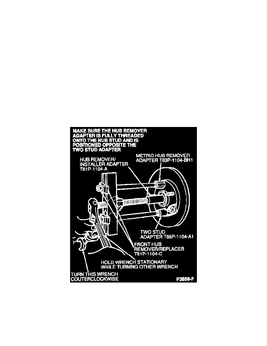
Front Hub Removal
11. Install Hub Remover/Installer Adapter T81P-1104-A with Front Hub Remover/Replacer T81P-1104-C and Wheel Bolt Adapters T83P-1104-BH1
and Two Stud Adapter T86P-1104-A1 or equivalent and remove hub, bearing and knuckle assembly by pushing out CV joint outer shaft until it is
free of assembly.
12. Support knuckle with a length of wire, remove strut bolt and slide hub/bearing/knuckle assembly off strut.
13. Carefully remove support wire, and carry hub/bearing/knuckle assembly to a bench.