
Taurus V6-182 3.0L FF (1995)
Anti-Lock Brake Control Module: Diagrams
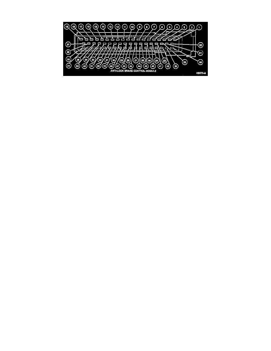
Connector
Pin
Circuit
Circuit Function
1
530 (LG/Y)
Ground
2
498 (PK)
ABS Valve Assembly
3
532 (O/Y)
ABS Power Relay
4
Not Used
5
549 (BR/W)
Anti-Lock Brake Pedal Sensor
Switch
6
Not Used
7
Not Used
8
542 (Y)
Brake Fluid Level Switch
550 (Y/LG)(*)
9
Not Used
10
Not Used
11
Not Used
12
Not Used
13
Not Used
14
Not Used
15
539 (PK/LB)
Anti-Lock Pump Motor Relay
16
Not Used
17
Not Used
18
492 (BR)
ABS Valve Assembly
685 (BK/W) (*)
19
530 (LG/Y)
Ground
20
495 (T)
ABS Valve Assembly
21
497 (W)
ABS Valve Assembly
22
Not Used
23
201 (T/R)
Data Link Connector
24
Not Used
25
Not Used
26
535 (LB/R)
ABS Switch to Level Switch
27
524 (PK/BK)
Right Rear Brake Anti-Lock
Sensor
28
519 (LG/BK)
Left Rear Brake Anti-Lock Sensor
29
516 (Y/BK)
Right Front Brake Anti-Lock
Sensor
30
522 (T/BK)
Left Front Brake Anti-Lock
Sensor
31
462 (P)
Pump Motor Speed Sensor
32
511 (LG)
Stoplight Switch
33
532 (O/Y)
ABS Power Relay
34
513 (BR/PK)
ABS Power Relay
35
Not Used
36
499 (GY/BK)
ABS Valve Assembly
37
Not Used
38
510 (T/R)
ABS Valve Assembly
39
Not Used